SLAA856A July 2018 – July 2021 TAS5825M
2.1 Spread Spectrum Modulation
EMI is electromagnetic radiation emitted by electrical systems with fast changing signals that are common to the outputs of a Class-D audio power amplifier. EMI encompasses two aspects: emission and susceptibility. Emission refers to the generation of unwanted electromagnetic energy by the equipment. Susceptibility, by contrast, refers to the degree in which the equipment is affected by the electromagnetic disturbances. EMC is achieved by addressing both emission and susceptibility issues. The TAS5825M device has advanced emission suppression technology which enables the device to run without an LC filter with speaker wires up to one meter long and still meet the EMI regulatory standards such as EN55022, CISPR 22, or FCC Part 15 Class B.
The TAS5825M device features an advanced spread spectrum modulation mode with low EMI emission to lower the overall system cost. This reduced system cost is achieved by replacing large expensive LC output filters with small, low-cost ferrite beads filters. The spread spectrum modulation scheme exhibits less EMI by flattening the wideband spectral components from the speaker cables and still retains the high-efficiency feature of a traditional Class-D amplifier.
Figure 2-1 shows the topology of a conventional (nonspread-spectrum) BD modulation Class-D amplifier. The BD switching technique uses an internally generated triangular waveform with a fixed frequency and a complementary signal pair at the input stage. The output PWM changes the duty cycle to generate a moving average of the signal that correspond to the input analog signal. The advantages of PWM switching topology is high efficiency, which provides low power consumption and small thermal design.
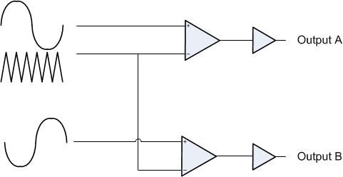 Figure 2-1 Class-D Audio Amplifier
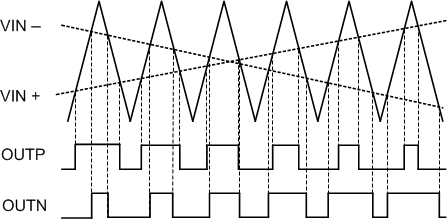 Figure 2-2 Fixed-Frequency Mode Modulation
The TAS5825M device features two modulation modes: fixed-frequency modulation mode (FFM) and spread spectrum modulation (SSM) mode. In the conventional FFM mode (Figure 2-1) the frequency of the triangular waveform is fixed as shown in Figure 2-2. In SSM mode, the frequency of the triangular waveform frequency varies cycle-to-cycle with a center frequency at switching frequency configured. SSM mode improves EMI emissions radiated by the speaker wires by spreading the energy over a larger bandwidth and reducing the wideband spectral content. On the other hand, FFM produces larger amounts of spectral energy at multiples of the PWM switching frequency. The cycle-to-cycle variation of the switching frequency does not affect the efficiency of the audio amplifier. Figure 2-3 shows the effects of the frequency variation on the triangular waveform.
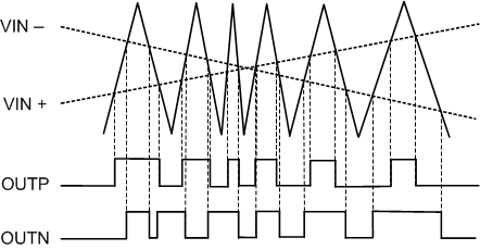 Figure 2-3 Spread Spectrum Mode Modulation
Compared to traditional FFM Class-D amplifier, the spread spectrum scheme has reduced the peak energy of the switching frequency and lessens harmonics. FFM Modulationshows a comparison of FFM and SSM modulation.
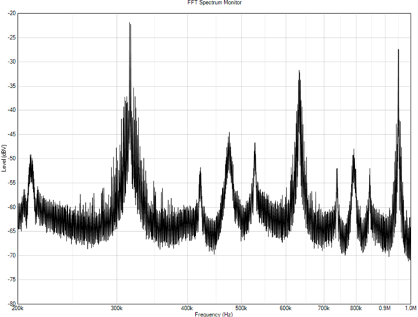 FFM Modulation
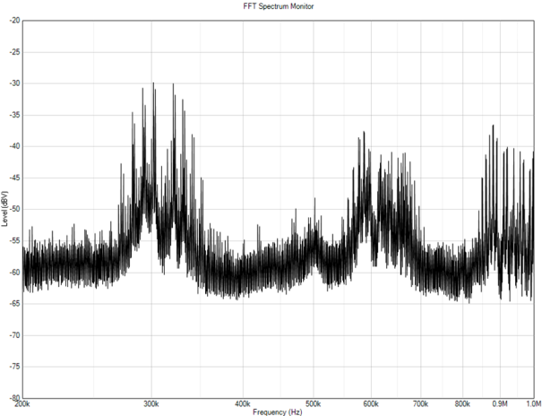 SSM Modulation