SLAA897 June 2019 MSP430FR2353 , MSP430FR2355
2.2 Using SAC as TIA and Gain Stage
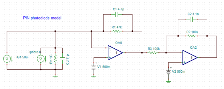
Figure 4 shows an approximate model of a photodiode and circuit for TIA with gain stage. The photodiode model assumes to have the received signal with both AC and DC components. For more details, see How to Design an SpO2 and OHRM System Using AFE4403. The first OA (OA0) forms a TIA stage converting the current signal in voltage terms followed by a gain stage (OA2) for amplification.
To configure SAC as a TIA, put PSEL=01, NSEL=00, MSEL=xx and connect photodiode, external resistor and capacitor (for filtering). For the subsequent gain stage, the SAC can be put in:
- General purpose mode (PSEL=00, NSEL=00, MSEL=xx) and using external resistors to set gain, or
- Inverting PGA mode (PSEL=01, NSEL=01, MSEL=00) and using internal programmable gain values
 Figure 4. Simulation of TIA and Gain Stage
 The outputs of the first stage can be sampled to regulate the LED brightness and, hence, the photodiode current in order to keep the OA from saturating. The sampled values can also be used for tracking the DC component of the photodiode signal and varying the DAC output of the second OA accordingly to extract only the AC component.