SLAAE50A January 2022 – October 2022 MSP430FR2533 , MSP430FR2533
3.2 Hardware Design
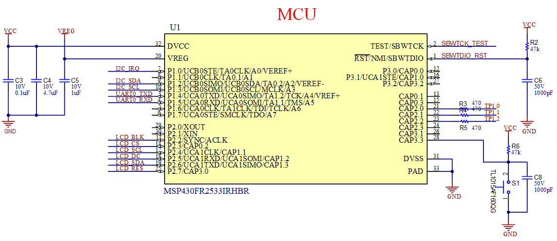
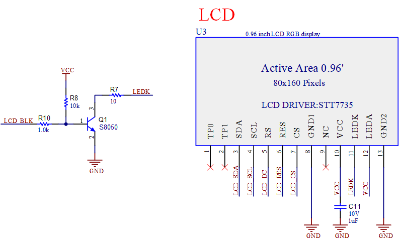
The hardware of this design mainly includes power supply, MCU, LCD display, and communication interface. The power supply converts 5-V USB to 3.3 V for the MCU. Figure 3-3 shows the design of the MCU and peripheral circuits. Figure 3-4 shows the LCD design. Communication protocol uses I2C and UART.
 Figure 3-3 Schematic Diagram of
MSP430FR2533
 Figure 3-4 Schematic Diagram of
LCD
Figure 3-4 Schematic Diagram of
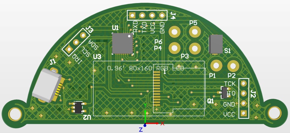
LCDFigure 3-5 shows the 3D PCB. Three electrodes are designed in this circuit, which are respectively used for environmental calibration, actual liquid level measurement and liquid level alarm prompt.
 Figure 3-5 PCB and Circuit Board of Liquid Level Measurement Application