SLAAEE6 October 2023 MSPM0L1306 , MSPM0L1306
6.2 Step2: Evaluation
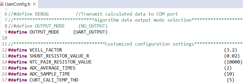
Before you start, there are some settings related to evaluation in UserConfig.h.
 Figure 6-1 Mode Setting
If you enable the definition of “DEBUG”, you can see the current calibration data output from the UART1.
For different output modes, “UART_OUTPUT” means enabling data output through UART1. Then you can observe the running parameters on the GUI. “NO_OUTPUT” means terminating the UART data output.
For customized configuration settings, you may need to make change for “VCELL_FACTOR”, “SHUNT_RESISTOR_VALUE_R” and “NTC_PAIR_RESISTOR_VALUE” according to your hardware setup.
The hardware test setup is shown in Figure 6-2. You need the MSPM0 Gauge board and a real battery for test. You can insert the battery into the socket and charge or discharge it on J2. You can also connect a power supply to J3 directly.
The detection data (Vcell, Icell, Tcell) comes from the MSPM0 analog peripherals. Then it sends the data to the GUI through UART1 on J4. The GUI can help to record the battery running data for further analysis.
In order to ensure the voltage of programming pins mach with the debug port of MUC, when programming the MSPM0, use a jumper to connect VMCU and VEx on J1. As the UART1 port supports up to 5 V input and output voltage, When evaluating, use a jumper to connect VMCU and VIn on J1.
 Figure 6-2 Hardware Setup and Connection