SLAAEE6 October   2023 MSPM0L1306 , MSPM0L1306


  1.   1
  2.   Abstract
  3.   Trademarks
  4. 1Introduction
  5. 2Hardware Introduction
  6. 3Software Introduction
  7. 4Gauge GUI Introduction
  8. 5Current Detection and Calibration Method
    1. 5.1 MSPM0 OPA Introduction
      1. 5.1.1 OPA input and output limitation
      2. 5.1.2 OPA Accuracy Influence
    2. 5.2 Current Detection Method
    3. 5.3 Current Calibration Method
      1. 5.3.1 (R1+R2)/R2 calibration
      2. 5.3.2 OPA1 Voffset calibration
      3. 5.3.3 R3/(R4+R3) calibration
      4. 5.3.4 Vref calibration
  9. 6Solution Evaluation Steps
    1. 6.1 Step1: Hardware Preparation
    2. 6.2 Step2: Evaluation
  10. 7MSPM0 Gauge Solution Test Results
    1. 7.1 Calibration Test Result
    2. 7.2 Current Detection Result
      1. 7.2.1 Test Under 25°C
      2. 7.2.2 Test Under 0°C
      3. 7.2.3 Test Under 50°C
      4. 7.2.4 Conclusion
    3. 7.3 Current Consumption Test
  11. 8Solution Summery and Improvement Direction
    1. 8.1 Shunter Resistor
    2. 8.2 ADC and its Reference
    3. 8.3 Runtime Calibration

Software Introduction

The software project is shown in Figure 3-1. The project and files related to the current detection has four parts. For other files, they are same for all the MSPM0 projects.
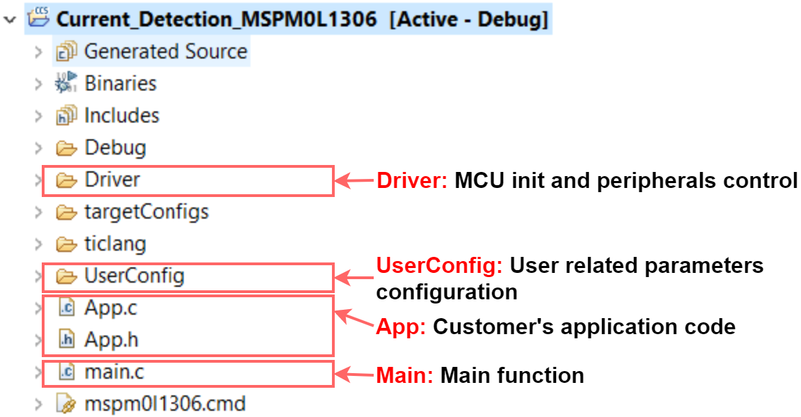
GUID-A80E4288-91D3-4ED3-BF18-213CC000FA38-low.pngFigure 3-1 Software Project View

For UserConfig part, it is included in Section 6.2. For the driver part, it includes all the MPSM0 peripheral initialization and low-level function. Section 5 provides a description on how the current detection work. For the App part, it includes the high-level software function calling, which is the place for customers to customize their own functions. For the Main part, it includes the highest system function code.