SLAU176E February 2006 – March 2019
-
eZ430-F2013 Development Tool
- Trademarks
- 1 eZ430-F2013 Overview
- 2 Kit Contents, eZ430-F2013
- 3 Software Installation
- 4 Hardware Installation
- 5 Flashing the LED Demo Using IAR Embedded Workbench IDE
- 6 Flashing the LED Demo Using Code Composer Studio IDE
- 7 Using the MSP430F2013 Target Board and Debugging Interface Independently
- 8 Where To Go For More Information
- 9 Frequently Asked Questions
- 10 Schematics
- Revision History
1 eZ430-F2013 Overview
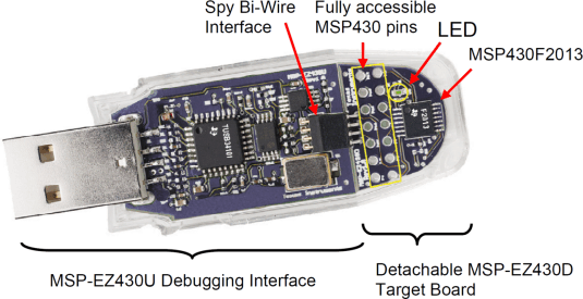
The eZ430-F2013 is a complete development tool for the MSP430™ MCU and provides all of the hardware and software that is required to evaluate the MSP430F2013 and complete an entire project in a convenient USB stick form factor. The eZ430-F2013 uses the IAR Embedded Workbench IDE or Code Composer Studio IDE to provide full emulation with the option of designing a stand-alone system or detaching the removable target board to integrate into an existing design. The USB port provides power to operate the ultra-low-power MSP430 so no external power supply is required.
All 14 pins on the MSP430F2013 are accessible on the MSP-EZ430D target board for easy debugging and interfacing with peripherals. Additionally, one of the digital I/O pins is connected to an LED for visual feedback. The MSP430F2013 includes 16-MIPS performance, a 16-bit sigma delta analog-to-digital converter, a 16-bit timer, watchdog timer, brownout detector, a USI module supporting SPI and I2C, and five low-power modes drawing as little as 0.5 µA standby.
 Figure 1. eZ430-F2013 Development Tool