SLAU601B March   2015  – April 2020


  1.   BOOSTXL-K350QVG-S1 QVGA Display BoosterPack™ Plug-in Module
    1.     Trademarks
    2. 1 Getting Started
      1. 1.1 Introduction
      2. 1.2 Key Features
      3. 1.3 What's Included
        1. 1.3.1 Kit Contents
        2. 1.3.2 Software Examples
      4. 1.4 Next Steps: Looking Into the Provided Code
    3. 2 Hardware
      1. 2.1 Hardware Features
        1. 2.1.1 BoosterPack Pinout
        2. 2.1.2 Kentec QVGA Display (K350QVG-V2-F)
        3. 2.1.3 SSD2119 LCD Driver
        4. 2.1.4 LCD Backlight Circuitry
        5. 2.1.5 SPI Configuration
      2. 2.2 Design Files
        1. 2.2.1 Hardware
        2. 2.2.2 Software
      3. 2.3 Hardware Change log
    4. 3 Software Examples
      1. 3.1 BOOSTXL-K350QVG-S1 + MSP-EXP432P401R Graphics Library Example
    5. 4 Additional Resources
      1. 4.1 TI LaunchPad Portal
      2. 4.2 Download CCS, IAR, Keil, or Energia
      3. 4.3 The Community
        1. 4.3.1 TI E2E™ Community
        2. 4.3.2 Community at Large
    6. 5 Schematics
  2.   Revision History

BoosterPack Pinout

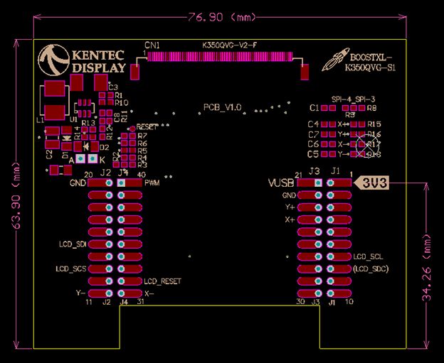
boosterpack_pinout.jpgFigure 3. BoosterPack Pinout (View From Bottom of PCB)

The Kentec QVGA Display BoosterPack adheres to the 40-pin LaunchPad and BoosterPack pinout standard. A standard was created to aid compatibility between LaunchPad and BoosterPack tools across the TI ecosystem.

The 40-pin standard is compatible with the 20-pin standard that is used by other LaunchPad kits like the MSP-EXP430FR4133. However, this BoosterPack is intended for use with 40-pin LaunchPad kits. If compatibility is needed with a 20-pin LaunchPad, some modifications must be made for access to certain pins and to provide 5 V for the LCD backlight circuitry.

More information about compatibility can also be found at http://www.ti.com/launchpad.