SLLA618 October 2023 ATL431 , ATL431LI , TL431 , TL431LI , TLVH432
4.1 Shunt Reference Implementation
The UCC28780EVM-021 EVM that was used to perform this experiment originally had an ATL431 shunt reference with a biasing resistance of 34 kΩ. Once test probes were installed, the average cathode voltage, VKA, under a 40 W load was measured to be 16.9 V. When a new shunt reference was soldered onto the board for testing, a new bias current had to be established. Equation 3 was used to calculate the new required biasing resistance, Rbias, where 16.9 V was assumed as the cathode voltage VKA for simplicity. IKA(min) was pulled from the new devices data sheet, and Vout was found using Equation 1. The cathode voltage, VKA, changes according to the programmed output voltage due to the required feedback current to set that output voltage. The TLVH432 has a lower internal reference of 1.24V, meaning that the programmed output voltage is much lower, so R2 was decreased to 10 kΩ to change the programmed output voltage to 19.855 V. The TLVH432's cathode voltage, VKA, was measured at 18.27 V under a 40 W load, which was then used in Equation 3 to calculate the bias resistance, Rbias. The biasing resistance and biasing current provided for each shunt reference for a 40 W load are shown in Table 4-1.
| Component | Rbias | Ibias (40 W load) | IKA(min) | Vout (expected) |
|---|---|---|---|---|
| TL431 | 1.5 kΩ | 0.99 mA | 1 mA | 18.59 V |
| TLVH432 | 14 kΩ | 105.9 µA | 100 µA | 9.10 V |
| ATL431 | 34 kΩ | 44 µA | 35 µA | 18.33 V |
| TL431LI | 1.5 kΩ | 0.99 mA | 1 mA | 18.32 V |
| ATL431LI | 19.1 kΩ | 77.96 µA | 80 µA | 8.35 V |
The following scope images show the steady state performance of each shunt reference under the three-load conditions.
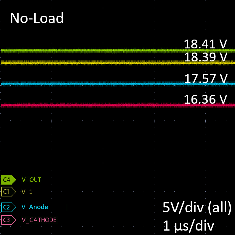 Figure 4-3 TL431 No-Load
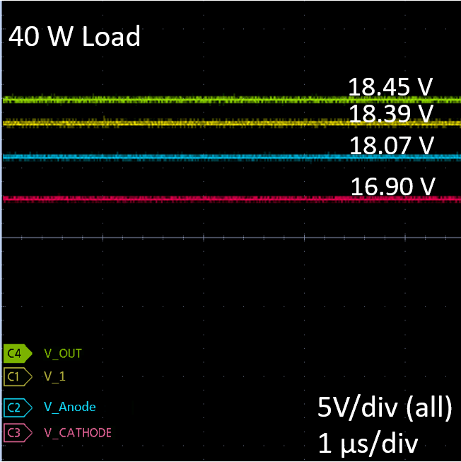 Figure 4-5 TL431 40 W Load
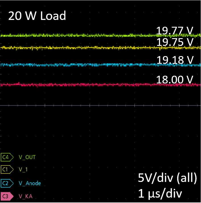 Figure 4-7 TLVH432 20 W Load
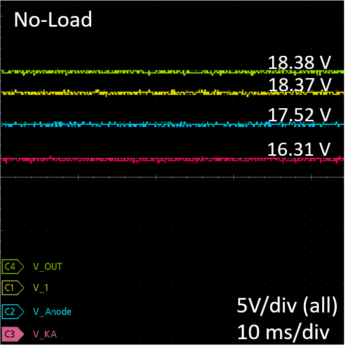 Figure 4-9 ATL431 No-Load
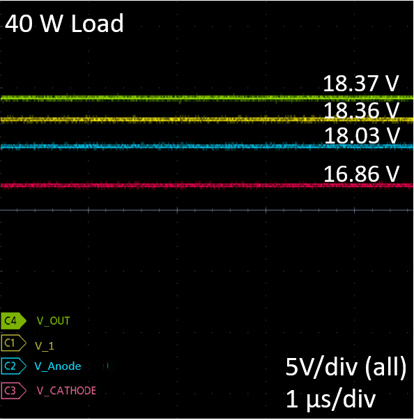 Figure 4-11 ATL431 40 W Load
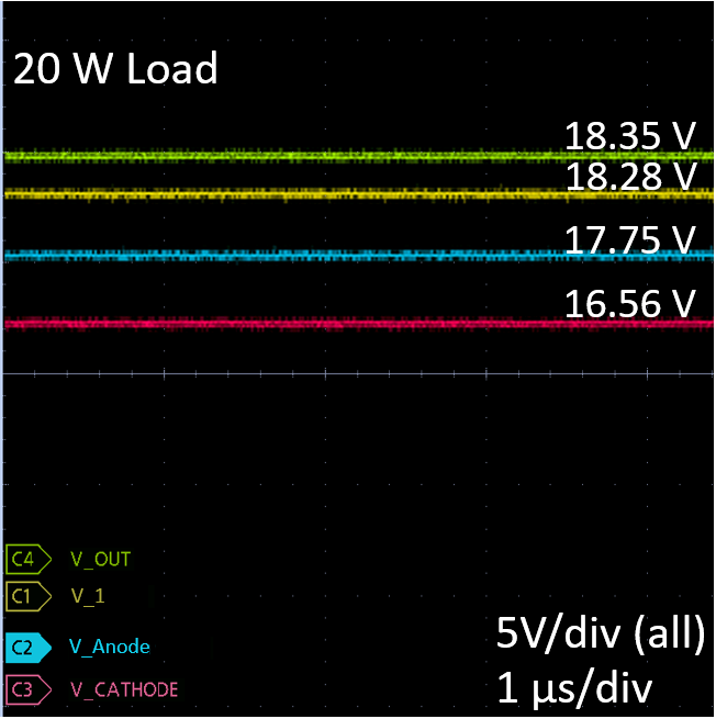 Figure 4-13 TL431LI 20 W Load
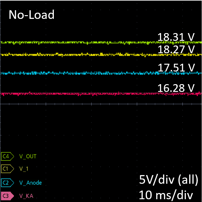 Figure 4-15 ATL431LI No-Load
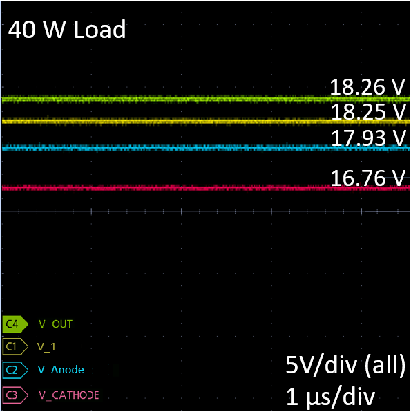 Figure 4-17 ATL431LI 40 W Load
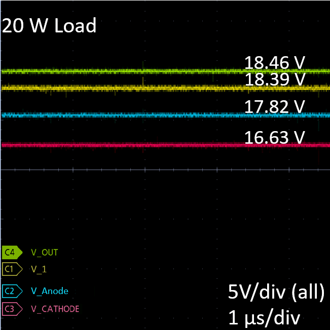 Figure 4-4 TL431 20 W Load
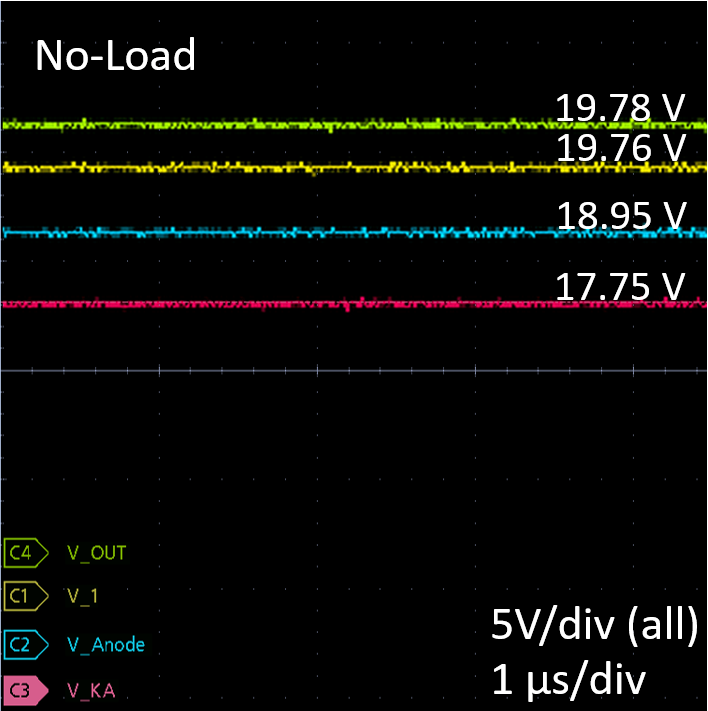 Figure 4-6 TLVH432 No-Load
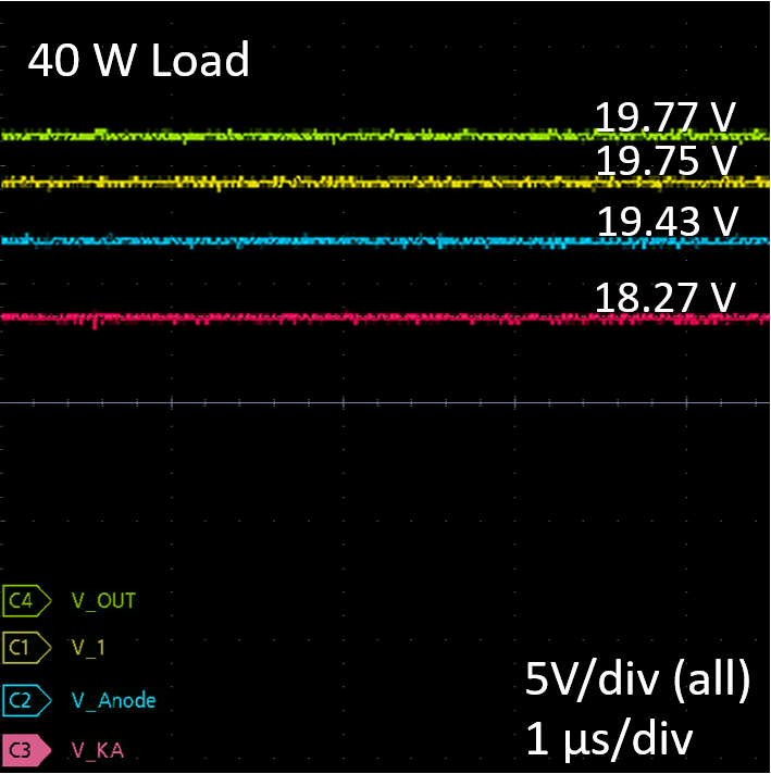 Figure 4-8 TLVH432 40 W Load
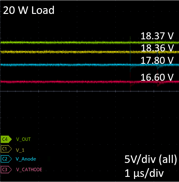 Figure 4-10 ATL431 20 W Load
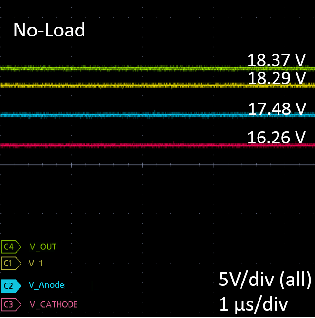 Figure 4-12 TL431LI No-Load
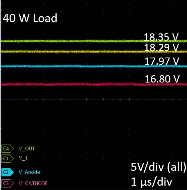 Figure 4-14 TL431LI 20 W Load
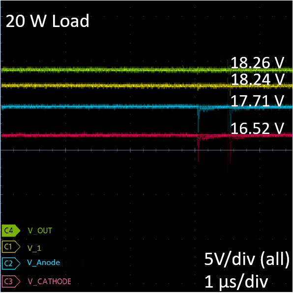 Figure 4-16 ATL431LI 20 W Load
Vout was measured as the expected programmed value for each of the plots shownand V1 was measured as a slightly lower value than Vout. VAnode and VKA change under different load conditions to modify the secondary side feedback current, IFB(secondary) , through the optocoupler diode. This change in VKA also decreases the biasing current, Ibias, being provided to the shunt reference under larger loads, which is why Ibias was established as IKA(min) at the full-load condition.