SLOA285A October 2019 – October 2020 ISO7741 , ISOW7841 , LM25037 , LM25180 , LM5180 , LM5181 , LM5181-Q1 , UCC12040 , UCC12050
1 Introduction
Patient safety is a global health priority. Recalling resolution WHA55.18 (2002), which urged Member States to “pay the closest possible attention to the problem of patient safety and to establish and strengthen science-based systems, necessary for improving patients’ safety and the quality of health care”, the seventy-second World Health Assembly (WHA72), in May 2019, adopted WHA72.6, a resolution on ‘Global action on patient safety’. (Source: https://www.who.int/patientsafety/en/)
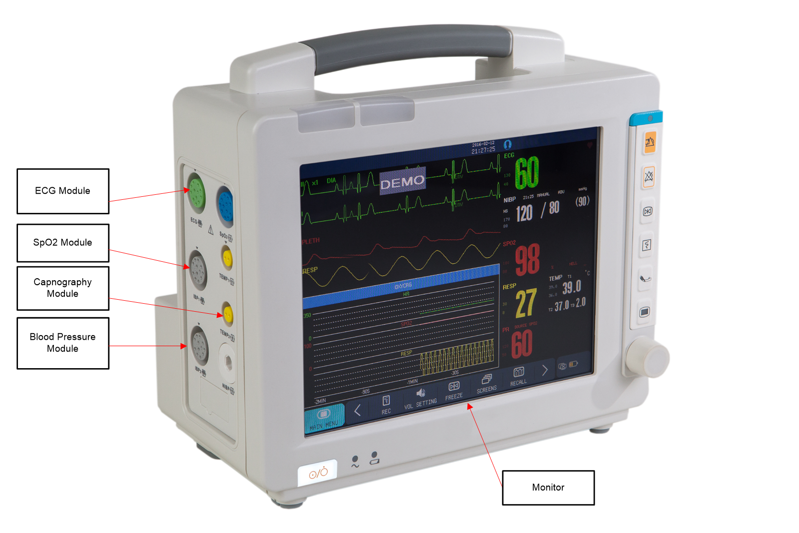
Multiparameter Patient Monitors measure human vital signs like Electrocardiogram (ECG), Blood Oxygen Concentration (% SpO2), blood pressure, temperature, and so forth(see Figure 1-1).
 Figure 1-1 Multi-Parameter Patient Monitor Showing How Modules are Connected to Main Monitor
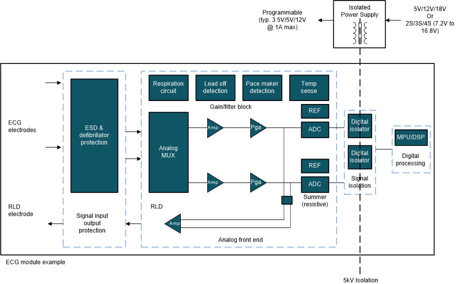
Figure 1-2 shows a generic block diagram of the ECG module. It highlights the isolation between the analog circuit and the digital processing unit. Medical standards (like IEC60601-1) specify that multiparameter patient monitors need to have isolation up to 5kV to separate the grounds, prevent any ground loop currents, and prevent leakage currents flowing from the patient’s body. While isolating data, it also needs the same level of isolation as on the power supply.
 Figure 1-2 Isolated ECG Module Block Diagram (showing isolation)
The data isolation can be done using simple digital isolators but the isolated power topology needs a thoughtful analysis. Table 1-1 shows the typical specs for such isolated power supplies.
| Characteristic | Value |
|---|---|
| Input voltage range | Option – 1: 3.3 V to 24 V from AC/DC power supply |
| Option – 2: From 1S-4S battery (i3.7 V to 16 V) | |
| Output Voltage | Option – 1: 3.3 V or 5 V |
| Option – 2: 3.5 V or 5.5 V to be followed by an Low Drop-out Regulator (LDO) | |
| Output power | Typical 5 watts to 7 watts |
| Isolation | 5 kV and above |
This application report dwells deeper into critical design challenges associated with isolated power and data such as output regulation, feedback mechanism, input voltage range, output power and size considerations along with suitable power architectures given below:
- Conventional and PSR Flyback – Wide input voltage (Vin) and adjustable output power (Pout)
- Open-loop and Closed-loop Push-Pull – Feedback mechanism and output regulation
- Integrated isolated power and data – form-factor constraint designs with limited Pout