SLOA313 May 2021 AFE7070 , AFE7071
2.8 Mitigate Frequency Variation With the NCO
As previously shown, the modulator correction performance depends on LO frequency. It is possible to use the internal NCO to provide some relief to the frequency tuning requirements. The integrated baseband filters facilitate driving the signal up to ±10 MHz around an LO set-point. In practice, the entire range cannot be used without incurring some amplitude roll off at the edges due to the filters. Generally speaking, the device achieves a flat response up to 80% of the bandwidth. This technique keeps the LO frequency fixed and varies the NCO to move the signal within a 16-MHz window. With three calibrated LO points you can cover almost 50 MHz of tunable bandwidth.
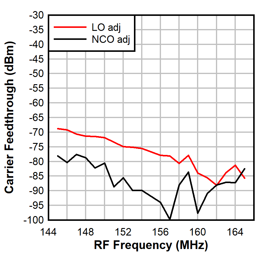
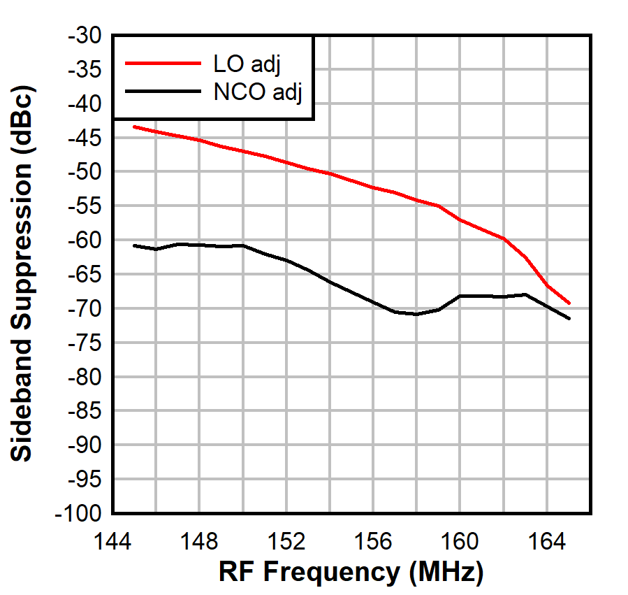
Figure 2-13 and Figure 2-14 compare the corrected CF and SBS performance when shifting the LO versus shifting the NCO. Performance with the NCO shift stays more consistent. In other words, the variation of the baseband signal and a fixed LO is more consistent than the other way around with the baseband fixed and the LO varied.
Using the NCO to shift over frequency offers a unique advantage in that QMC frequency correction is likely not needed. The fixed LO frequencies are calibrated out for best performance. Further, the temperature slope adjustment with respect to frequency is also not needed. This provides an easier, more consistent response without incurring the tolerance error of the frequency control algorithm.
 Figure 2-13 CF Over NCO and LO
Adjustment
 Figure 2-14 SBS Over NCO and LO
Adjustment