SLUA450A January 2008 – November 2022 BQ27421-G1 , BQ27425-G2A , BQ27425-G2B , BQ27441-G1 , BQ27505-J2 , BQ27505-J3 , BQ27505-J4 , BQ27505-J5 , BQ27520-G4 , BQ27530-G1 , BQ27531-G1 , BQ27545-G1 , BQ27546-G1 , BQ27741-G1 , BQ40Z50 , BQ40Z50-R1 , BQ40Z50-R2
- Theory and Implementation of Impedance Track™ Battery Fuel-Gauging Algorithm in bq2750x Family
- Trademarks
- 1Summary of the Algorithm Operation
-
2Parameters Updated by the Gas Gauge in More Detail
- 2.1 Modes of Algorithm Operation
- 2.2 Update of Chemical Depth of Discharge (DOD)
- 2.3 Update of Qmax
- 2.4 Update of Resistance
- 2.5 Update of Temperature Model
- 2.6 Update of DataRAM.Remaining Capacity (RM) and DataRAM.Full Charge Capacity (FCC)
- 2.7 Update of DataRAM.Remaining Capacity( ) and DataRAM.State Of Charge( ) Values
- 3Real Application Example
- 4Revision History
2.2 Update of Chemical Depth of Discharge (DOD)
The gas gauge updates information on chemical depth of discharge (DOD0) based on open-circuit voltage (OCV) readings when in a relaxed state. DOD is found by correlating DOD with OCV using a predefined table DOD(OCV,T) stored as reserved data flash parameters. The table is specific for a particular chemistry such as LiCoO2/carbon, LiMn2O4/carbon etc., and can be identified by reading the chemistry ID through sending ChemID( ) command 0x0008, then reading ChemID(). The gas gauge can be set up for a particular chemistry by using a specific firmware file (*.senc) that can be downloaded from bq2750x production folder on power.ti.com. The chemistry profile also can be programmed into bq2750x using the bqEASY wizard.
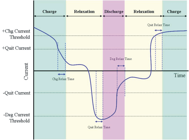
 Figure 2-1 Example of Algorithm Operation Mode Changes With Varying DataRAM.Average Current( )
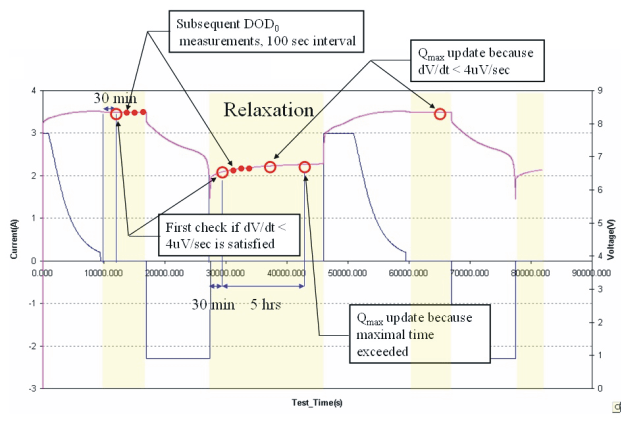
Figure 2-2 shows the timing of parameter updates during relaxation mode. After a 30-minute relaxation period is passed, the dV/dt <4 μV/s condition is checked. Once it is satisfied, OCV readings are taken. After that, OCV readings continue to be taken every 100 seconds. DOD is calculated based on each measured OCV reading using linear interpolation DOD = f(OCV,T). Integrated PassedCharge is set to zero at each DOD0 update.
 Figure 2-2 Timing of DOD0 and Qmax Updates During Relaxation Mode
If the current during the OCV reading is non-zero, then an IR correction is done. The first iteration of DOD is found from the uncorrected OCV reading; then the resistance value is found from the R(DOD) table and used to correct the OCV value as OCV`=OCV-I*R. Then, the corrected DOD is found from OCV`. This method achieves the best accuracy if the current during relaxation mode is below a C/20 rate. This is why it is recommended that the DF.Quit Current not exceed C/20.
If no DOD0 has been measured until the relaxation state is exited, the previous DOD0 is used along with the PassedCharge integrated since the last DOD reading.
During charge and discharge modes, the present DOD is recalculated every second as DOD = DOD0 + PassedCharge/Qmax. DOD is used for determining when a resistance update needs to occur, as well as the starting point for a Remaining Capacity (and FCC) calculation. Remaining capacity calculations occur immediately after discharge onset, at every resistance update, and after entering relaxation mode