SLUAA51 October 2020 LMR50410
3 Loop Stability Test Circuit and Simulation in PSpice
In a loop stability test, the frequency response analyzer draws Bode plot not by obtaining open-loop transfer function but by directly calculating on the gain and phase shift of the output and input signal. The process can be described in Figure 3-1.
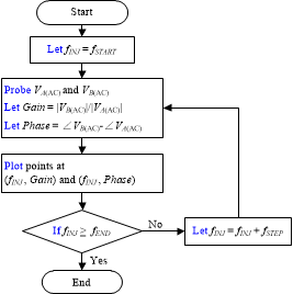 Figure 3-1 Frequency Sweeping Process in
Loop Stability Test
Figure 3-1 Frequency Sweeping Process in
Loop Stability TestIn Figure 3-1, fINJ is injection signal frequency, [fSTART, fEND] is frequency sweep range, VA(AC) and VB(AC) are AC components of voltages at injection and output voltage points.
In PSpice, a loop stability test simulation follows the same process. Consider a synchronous buck converter with a typical peak current mode control, shown in Figure 3-2.
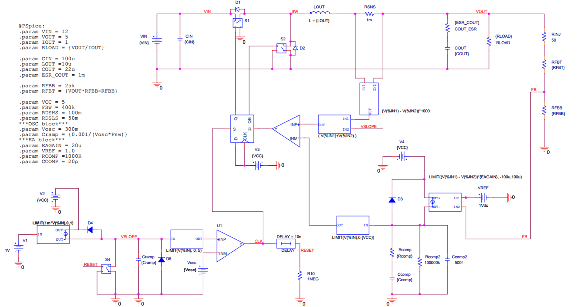 Figure 3-2 Synchronous Buck Converter
with Peak Current Mode Control in PSpice
Figure 3-2 Synchronous Buck Converter
with Peak Current Mode Control in PSpiceThe open-loop transfer function is derived in the reference application note SNVA793. When taking the parameters of the circuit in Figure 3-2 into its transfer function, the theoretical Bode plot can be obtained shown in Figure 3-3.
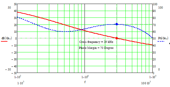 Figure 3-3 Calculated Bode Plot of Buck
Converter with Peak Current Mode Control
Figure 3-3 Calculated Bode Plot of Buck
Converter with Peak Current Mode ControlWhen making a loop stability simulation, the circuit connection of ripple injection should be same as a practical loop test. Also, the part of frequency response analyzer function which is performing sweeping also needs to be achieved by PSpice commands. With these considerations, the simulation circuit is shown in Figure 3-4.
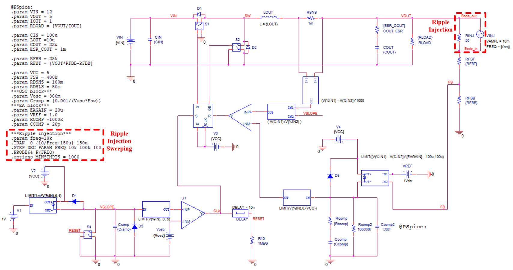 Figure 3-4 Loop Stability Test Circuit
and Commands of Synchronous Buck Converter in PSpice
Figure 3-4 Loop Stability Test Circuit
and Commands of Synchronous Buck Converter in PSpiceIn Figure 3-4, an AC voltage source is connected in parallel with a typical 50-Ohm resistor. The voltage should be very low so that the DC operating point of converter won’t be changed. A 10mV-amplitude source is applied in this case. The frequency of AC source will be on sweep so a variants freq is used. With the proper connection of ripple injection, frequency sweeping is achieved by PSpice commands which are listed in the red box. The below are detailed descriptions of the commands.
Line 1: .param freq = 10k
Line 1 is the definition of freq and it also sets the default value.
Line 2: .TRAN 0 {10/Freq+150u} 150u
On Line 2, simulation time at a single frequency point is defined. Normally it starts from 0 to a certain time after the converter reaches steady operating. In this case, the buck converter works steadily after 150 us. Before it, it’s on start-up and not suitable for a loop test. After 150 us, the remaining simulation time is 10 cycles at present frequency. 10 cycles are long enough for the simulator to calculate the gain and phase shift on input and output signals.
Line 3: .STEP DEC PARAM FREQ 10k 100k 100
Line 3 defines the total range and steps of frequency sweep. In this case, the sweep starts from 10 kHz and ends at 100 kHz. The steps number is 100 in each 10 times. So there will be totally 100 steps from 10-kHz to 100-kHz range.
Line 4: .PROBE64 P(FREQ)
Line 4 is probe and plot command in PSpice.
Line 5: .options MINSIMPTS = 1000
Line 5 specifies the minimum number of points per section in simulation output.
When running the simulation, a cluster of waveforms will be simulated and loaded on the probe window. Choose the FRA function and use the waveform data file, respectively set trace 1 and 2 by Bode-out and Bode_in net. Then the Bode plot can be processed, shown in Figure 3-5.
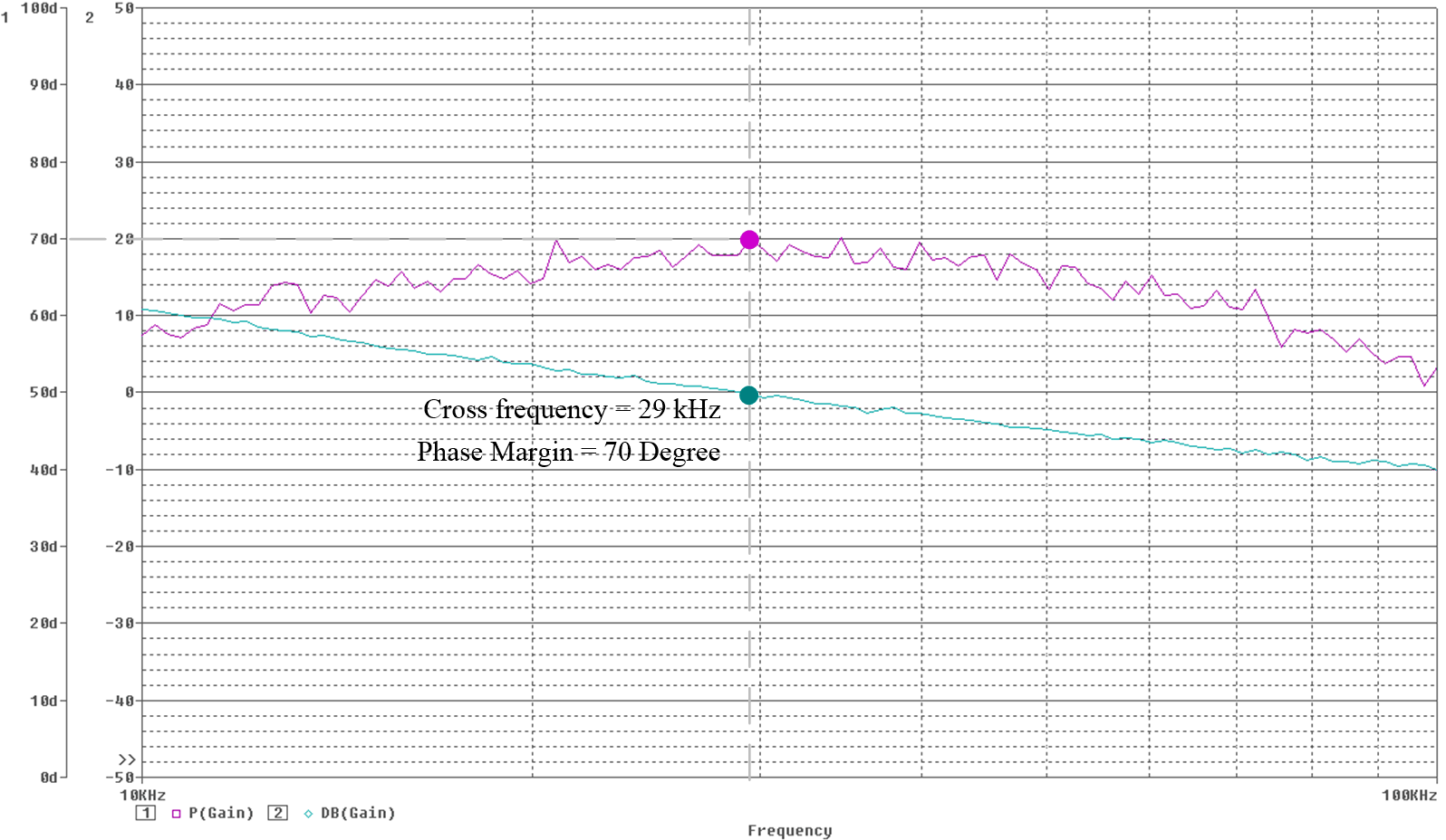 Figure 3-5 Calculated Bode Plot of Buck
Converter with Peak Current Mode Control
Figure 3-5 Calculated Bode Plot of Buck
Converter with Peak Current Mode ControlThe simulated Bode plot has little deviation compared with the calculated one. Thus, it verifies the loop test injection circuit and frequency response analyzer modeling so that can be applied in any kinds of DC-DC converter simulations with transient PSpice models.