SLUAAE4 May 2021 TPS563211
3.2 TPS563211 EVM Bench Test
The bench tests are done on the TPS563211EVM. For details, see the TPS563211EVM Evaluation Module User's Guide. The bench test setup and configuration is listed inTable 3-1 .
Table 3-1 Bench Setup for TPS563211
| VOUT(V) | L (µH) | Cout (µF) | Rtop (kΩ) / R9 | Rbot (kΩ) / R8 | Mode |
|---|---|---|---|---|---|
| 5 | 4.7 | 2× 22 µF (0805, 10 V) | 73.2 | 10 | FCCM / 600 kHz |
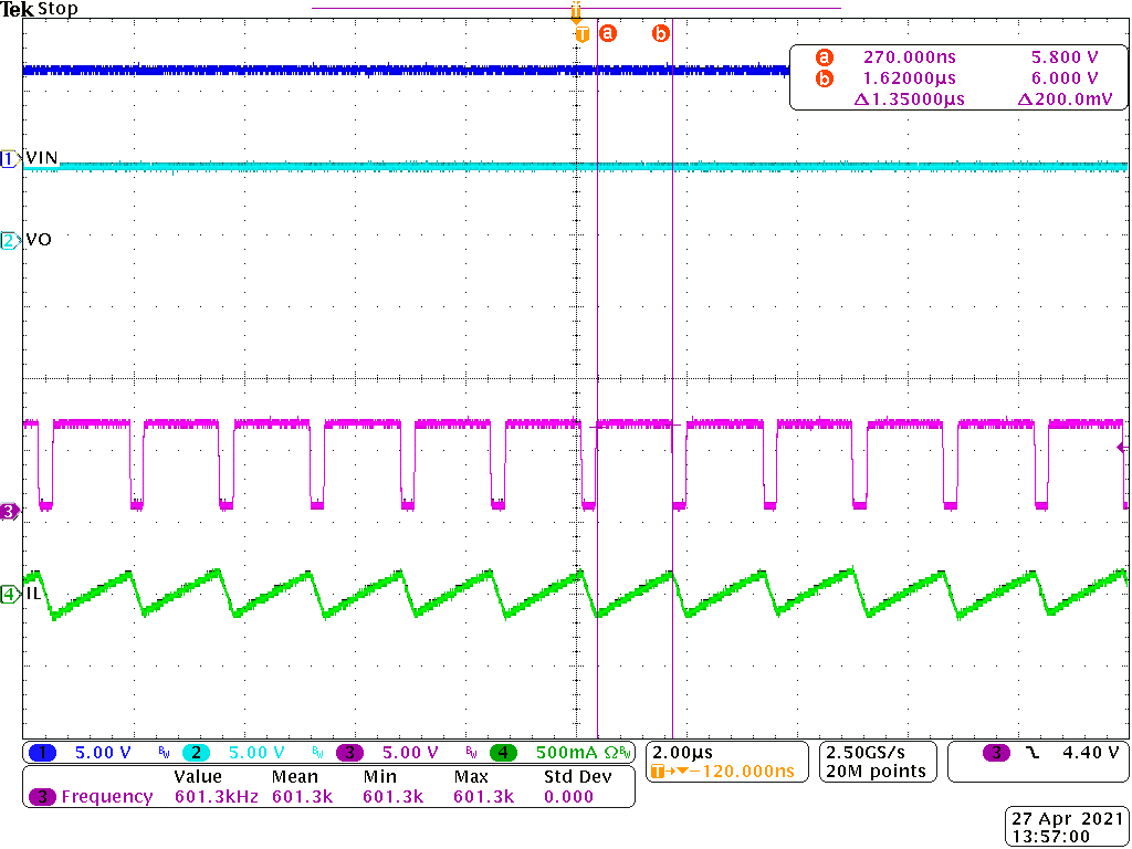
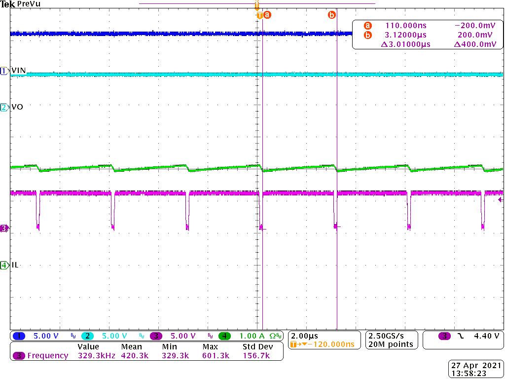
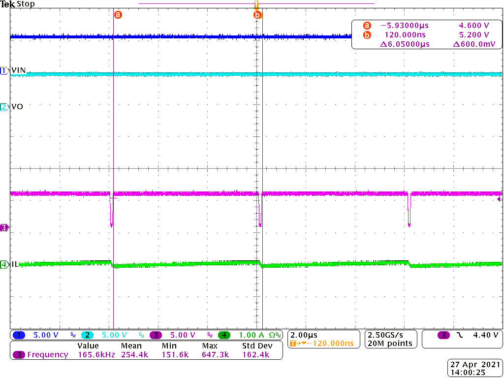
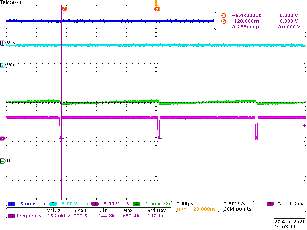
The waveforms in Figure 3-1 to Figure 3-4 show the behaviors with and without the ON-time extension function triggered. Table 3-2 lists the summary for the figures.
Table 3-2 Summary for TPS563211 On-Time Extension Bench
Test
| VOUT (V) | Figure | IOUT (A) | VIN (V) | VOUT / VIN Condition | TON Condition | FSW (kHz) |
|---|---|---|---|---|---|---|
| 5.09 | Figure 3-1 | 0 | 6 | 84% | Without ON-time extension, TON=1.38uS | 601 |
| 5.08 | Figure 3-2 | 3 | 5.79 | 87.7% | With ON-time extension, TON=1.9uS | 329 |
| 5.09 | Figure 3-3 | 0 | 5.18 | 98.3% | With ON-time extension,TON=6uS | 166 |
| 5.07 | Figure 3-4 | 3 | 5.55 | 91.4% | With ON-time extension,TON=6.5uS | 153 |
 Figure 3-1 6Vin-5Vout-0A
 Figure 3-2 6Vin-5Vout-3A
 Figure 3-3 5.1Vin-5Vout-0A
 Figure 3-4 5.5Vin-5vout-3A