SLUU240B January   2006  – March 2022 TPS51120


  1.   Trademarks
  2. 1Description
  3. 2Electrical Performance
  4. 3Schematic
  5. 4Test Setup and Results
    1. 4.1 Test Setup
    2. 4.2 Test Procedure
    3. 4.3 Start-Up Performance
    4. 4.4 Transient Performance
  6. 5Configuration
    1. 5.1 Switching Frequency Selection
    2. 5.2 Skip Mode and Faults Disable Selection
    3. 5.3 Output Voltage Setting Selection
    4. 5.4 Control Scheme Selection
  7. 6EVM Assembly Drawing and PCB Layout
  8. 7List of Materials
  9. 8References
  10. 9Revision History

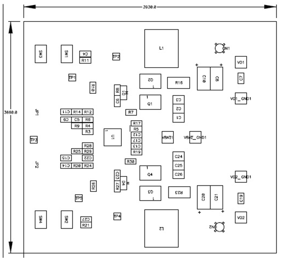
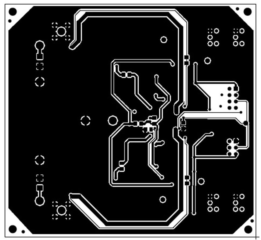
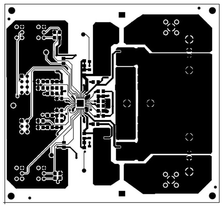
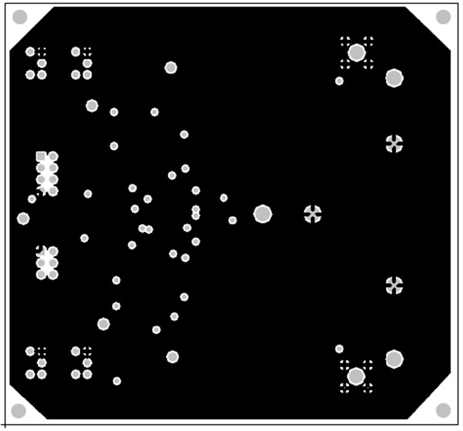
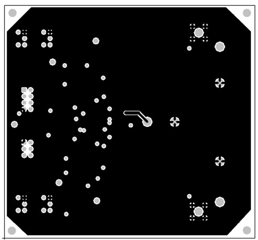
EVM Assembly Drawing and PCB Layout

GUID-20220303-SS0I-XCFC-0BKH-LNSQ2BTL7PQ5-low.png Figure 6-1 Top Assembly
GUID-20220303-SS0I-B4NM-NVKW-QW6PZWPG0DVW-low.png Figure 6-2 Bottom Assembly
GUID-20220303-SS0I-DSR6-9JKZ-ZNPZ1XPJDFL9-low.png Figure 6-3 Top Layer
GUID-20220303-SS0I-C3VW-94BN-VZRXCPRHGLJD-low.png Figure 6-4 Inner Layer 1
GUID-20220303-SS0I-0M1F-C7JX-NW9L4DRBSWHP-low.png Figure 6-5 Inner Layer 2
GUID-20220303-SS0I-B4NM-NVKW-QW6PZWPG0DVW-low.png Figure 6-6 Bottom Layer