SLUUBG6 May 2017
2.3 Equipment Setup
Use the following guidelines to set up the equipment:
- Set power supply #1 for 10-V DC, 5-A current limit and then turn off the supply.
- Connect the output of power supply #1 in series with a current meter to J1 (VIN and GND).
- Connect a voltage meter across J1 (VIN) and J1 (GND).
- Connect load #1 in series with a current meter to J6 (VSYS and GND). Connect a voltage meter across J6 (VSYS and GND). Set 1 A at the constant current mode. Turn off load #1.
- Connect Load #2 in series with a current meter to J5 (VBAT and GND). Connect a voltage meter across J5 (VBAT and GND). Set 7 V at KEPCO load output. Turn off Load #2.
- Connect J3 to the EV2400. Connect J3 to the SMBus PORT 1 (bq25700A) or I2C PORT 2 (bq25703A) on the EV2400. The connections are shown in Figure 1.
- Install jumpers as “JUMPER SET UP”.
- Turn on the computer and power supply #1. Open the bqstudio software.
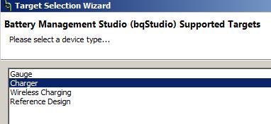
- Select Charger and click the Next button.
- For SMBus bq25700A, select “Charger_1_00-bq25700ASMB.bqz” on the Select a Target Page. For I2C bq25703A, select “Charger_1_00-bq25703AI2C.bqz” on the Select a Target Page.
- After selecting the target device, change “update mode” from “immediate” to “manual”, click “Read Register” and the following interface is presented.
NOTE
Add a 47-µF capacitor on the BAT pin when testing without real battery.

The picture shows the SMBus version EVM connection. If using the bq25703AEVM-732, move the connector to the I2C port.
Figure 1. EV2400 Connections After completing these steps , the test setup for PWR732 is as shown in Figure 2.
") Figure 2. Original Test Setup for PWR732 (bq2570x EVM)
Figure 2. Original Test Setup for PWR732 (bq2570x EVM)  Figure 3. Main Window of the bq2570x Evaluation Software