SLUUCW6 November   2023 LM74930-Q1


  1.   1
  2.   Description
  3.   Features
  4.   Applications
  5.   5
  6. 1Evaluation Module Overview
    1. 1.1 Introduction
    2. 1.2 Kit Contents
    3. 1.3 Specification
    4. 1.4 Device Information
  7. 2Hardware
    1. 2.1 Test Points and Connectors
    2. 2.2 Test Equipment and Setup
      1. 2.2.1 Power Supplies
      2. 2.2.2 Meters
      3. 2.2.3 Oscilloscope
      4. 2.2.4 Loads
    3. 2.3 Test Setup and Procedures
      1. 2.3.1 Power-up and Power-down with Input Voltage
      2. 2.3.2 Unsuppressed Load Dump 200 V - Output Clamp
      3. 2.3.3 Overcurrent Protection Test
      4. 2.3.4 Output Hot-Short Test
  8. 3Hardware Design Files
    1. 3.1 Schematic
    2. 3.2 PCB Layouts
    3. 3.3 Bill of Materials (BOM)
  9. 4Additional Information
    1.     Trademarks

Power-up and Power-down with Input Voltage

Use the following instructions to capture the precharging current profile.

  1. Set the input supply voltage VIN to 12 V and current limit of 10 A.
  2. Verify that the J5 jumper setting is set to 1-2.
  3. Turn ON the input power supply.
  4. Observe the start-up profile of charge pump voltage VCAP, HGATE, DGATE and output voltage.
  5. Turn OFF the input power supply.
  6. Observe the shutdown profile of charge pump voltage (VCAP– VVS), output voltage, HGATE, and DGATE.
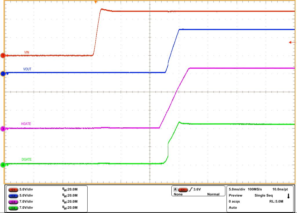
Figure 3-2 shows an example of power-up with EN profile captured on the LM74930Q1EVM evaluation board.
GUID-20231023-SS0I-CXR9-JKNM-T8KP9VKJKJ0P-low.jpg Figure 2-2 LM74930-Q1 Start-Up With VIN - HGATE, DGATE and VOUT
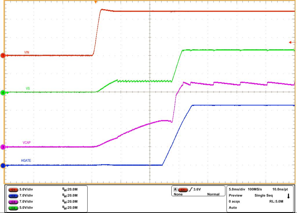
GUID-20231023-SS0I-101K-R6TQ-1T7X03XNMR6N-low.jpg Figure 2-3 LM74930-Q1 Start-Up With VIN - VS, CAP and HGATE