SLVAEG3B August 2019 – November 2022 DRV5011 , DRV5013 , DRV5015 , TMAG5115
To actualize motion in a system, various motor types can be used, such as brushed direct current (DC) motors, brushless DC motors (BLDC), alternating current (AC) motors, universal motors, stepper motors, or servo motors. From these options, BLDC motors specifically have the following advantages:
- High efficiency
- Reliability and long lifetime
- Compact size
- Low noise
- Support for a wide range of motor speeds
- No generation of sparks
The many advantages of BLDC motors are why this type of motor is used for a variety of applications, which include: cordless power tools, air conditioner output units, and automated door and gates in building security systems. BLDC motors are also used in various places within a car, such as sliding door modules, window modules, roof motor modules, wiper modules, seat position and comfort modules, engine fans, and pumps.
BLDC Commutation
Going into the details of how a BLDC motor works, Figure 1-1 shows a simplified model of a BLDC motor, which uses two magnet poles (one north and one south) and three coils. In this model, a permanent magnet on the rotor (the rotating part of the motor) is surrounded by coils on the stator (the stationary part of the motor). The movement of the magnet is what causes the rotor to move. The coils will change their magnetic poles (either north or south) depending on the direction of the current that is injected into them. The attraction of the electromagnet to the opposite pole of the permanent magnet and the repulsion of the electromagnet to the same pole of the permanent magnet causes the permanent magnet and rotor to move, thereby producing torque.
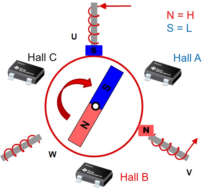 Figure 1-1 BLDC Motor Model, Commutation Step 1
As an example, if the magnet is in the position shown in Figure 1-1 and it is desired to cause the magnet to move in the clockwise direction, inject coil U with a current to act like the south pole of a magnet and inject coil V with a current to act like the north pole of a magnet. The south pole generated by coil U repulses the south pole of the permanent magnet and the north pole generated by coil V attracts the south pole of the permanent magnet, thereby causing the permanent magnet and rotor to rotate clockwise until it reaches the magnet position shown in Figure 1-2. From the magnet position of Figure 1-2, injecting current into coil W to act like the north pole of a magnet and injecting current to coil U to continue to act like the south pole of a magnet, causes the rotor to rotate clockwise again. To keep the magnet and rotor continuously moving along the circle, current has to be successively injected into the different coils in a very specific sequence. The process of switching which coils have current injected in them to cause rotor motion is called commutation.
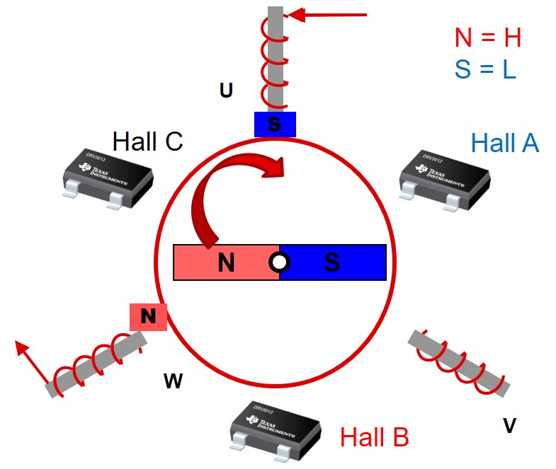 Figure 1-2 BLDC Motor Model, Commutation Step 2
As Figure 1-1 and Figure 1-2 show, the appropriate coils to inject current into and the polarity of these currents depends on the current position of the magnet. BLDC commutation schemes work by first determining where the rotor is and then using this rotor position information to apply a magnetic field to move the rotor in the desired direction. There are two methods to determine the rotor position. The first approach uses a position sensor. The second approach is a sensorless method that determines position based on back electromotive force (EMF), which is a voltage that is generated on the motor while it is spinning. The amplitude of the generated back-EMF waveform on a motor is proportional to the speed of the motor.
The advantages of sensored commutation include the following:
- Since the amplitude of the generated back-EMF waveform on a motor is proportional to the speed of the motor, a sensorless commutation scheme is not operable at low speeds because the back-EMF would be too small to measure to determine the rotor position. If a system requires significant torque at zero speed, sensored commutation is necessary.
- At very high motor speeds, it is difficult to differentiate the different transitions when back-EMF is used. Use sensored commutation if the motor moves at very high speeds to alleviate this issue.
- Sensored implementations are relatively simple to execute and do not require complex calculations like sensorless implementations.
For sensored commutation, Hall position sensors, encoders, or resolvers can be used. Among these options, Hall position sensors are most common due to their relatively low cost. From the different types of Hall position sensors, Hall latches are used to provide a simple six step method for commutation. With these Hall latches, alternating north and south poles are required to toggle the output of a device, as illustrated in Figure 1-3.
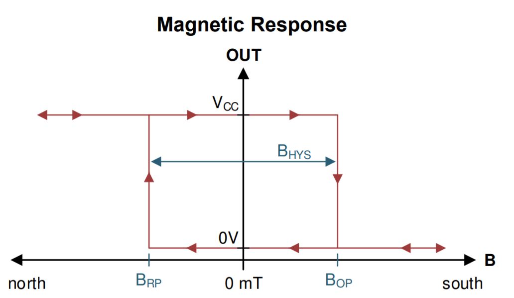 Figure 1-3 Output of a Hall Latch
For the latch shown in Figure 1-3, the output is only asserted low when the device detects the south pole of a magnet and the magnitude of the sensed magnetic flux density is greater than the magnetic flux density operating point, which is referred to as BOP in the figure. The output would stay low until the device detects the north pole of the magnet and the magnitude of the sensed magnetic flux density is greater than the magnetic flux density release point of the latch, which is referred to as BRP in the figure. In the absence of magnetic input, the last state of the latch remains active.
Figure 1-4 shows the output waveform of a sensored six-step motor commutation control scheme using three Hall latches. In this scheme, only two phases are driven at a time, where the third phase is in a high-Z state. In the figure, the numbers represent the commutation step. Step 1 specifically corresponds to the state shown in Figure 1-1 and step 2 corresponds to the state shown in Figure 1-2. The Hall A, Hall B, and Hall C waveforms in Figure 1-4 correspond to the output of the Hall latches during the different commutation steps. The Phase U, Phase V, and Phase W waveforms represent the waveforms to apply to the phase in order for the magnet to move to its next commutation step. In Figure 1-4, a “+” corresponds to injecting a current so that a south pole is applied to the phase, a “-“ corresponds to injecting an opposite current so that a north pole is applied to the phase, and “Z” refers to the phase that is in a high-Z state. This figure illustrates that there are six independent Hall states, where each state corresponds to a different option for driving the phases to keep the motor spinning. Therefore, the Hall states can be used to provide information on how to drive the phases to keep the motor spinning, where the state of the Hall sensors can be used as indexes into a software lookup table to get information on how to drive the different phases based on the current position of the rotor.
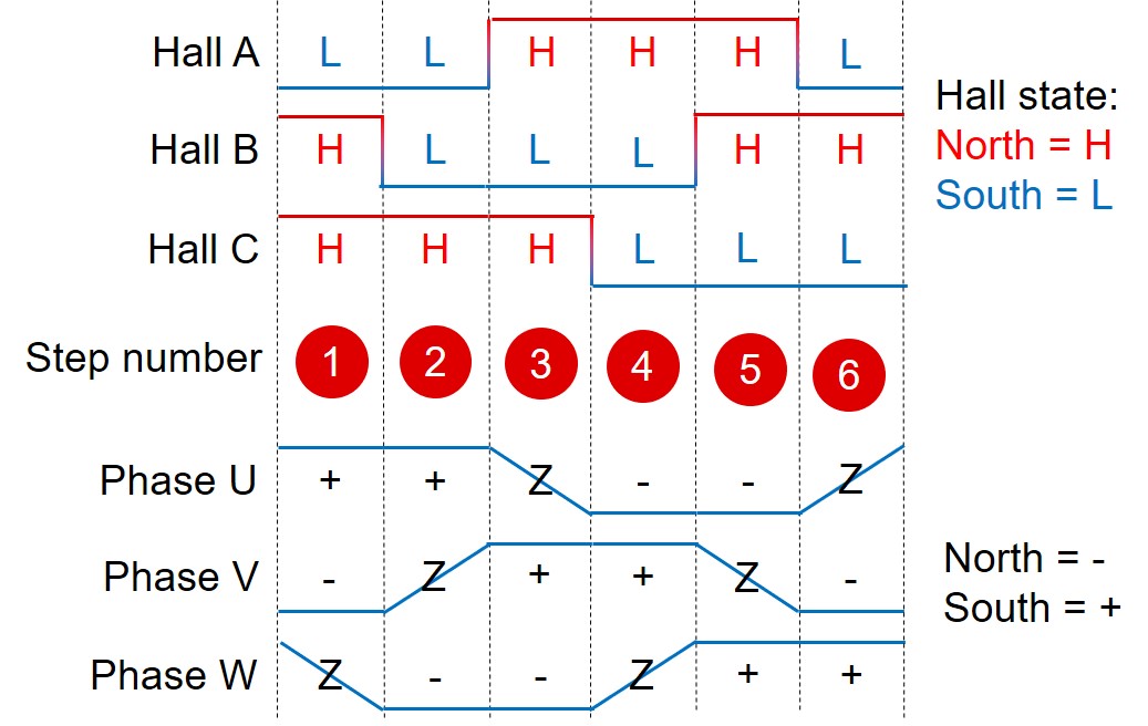 Figure 1-4 Six-Step Motor Commutation Control Scheme
The previous examples use a simplified model for a BLDC motor. Typically, BLDC motors have more magnet poles and coils than displayed in the figures. The more coils and rotor magnetic poles that are used, the finer the control of the magnet. The magnets can be implemented as multiple bar magnets adjacent to each other, where adjacent magnets have opposite polarity from each other. Using more magnets increases the number of state transitions seen by the Hall sensor in a given time, thereby decreasing how much the rotor has to rotate for the Hall sensors to cycle through all their possible states.
The three Hall position sensors should be placed so that the angle differences between their respective outputs are 120 ° offset from each other. This angle is referred to as the electrical angle, which may differ from the actual angle at which the devices are mechanically placed from each other. From the center of the motor axis, the number of degrees to space each sensor (the mechanical angle) can be set to 2 / [number of poles] × 120° to create the necessary 120 electrical degrees.
In the simplified two-pole examples in Figure 1-1 and Figure 1-2, the mechanical and electrical angles are equal. However, for systems that have more magnet poles, the electrical angle and mechanical angle are not equal due to the increased number of magnet poles decreasing the time to cycle through the different Hall output state combinations. To illustrate this, suppose there are 12 magnet poles (6 north poles and 6 south poles) in a system. To obtain 120 electrical degree separation between the Hall latches in this 12-pole system, the Hall position sensors can be placed so that they are mechanically ±20 degrees from each other.
BLDC Motor System Architecture
Figure 1-5 shows a system implementation for BLDC motor control. Three half-bridge circuits are used to connect the motor phases to VCC or GND, thereby injecting current in the coils to create the necessary magnetic fields for the different phases. In this system, a motor controller is used to dictate commutation. The controller can be a microcontroller, FPGA, DSP, digital state machine, or a pure analog implementation. The motor driver is used to allow the control block to interface with the half-bridge circuits, thereby allowing the motor driver to dictate commutation through the half-bridge circuits. The Hall position sensors provide information on the location of the rotor to the motor controller, which the motor controller uses to determine how the half-bridge circuits should be driven. As an alternative to the system architecture shown in Figure 1-5, some motor drivers have integrated half-bridge circuits so that the external half-bridge circuits shown in the figure are not necessary.
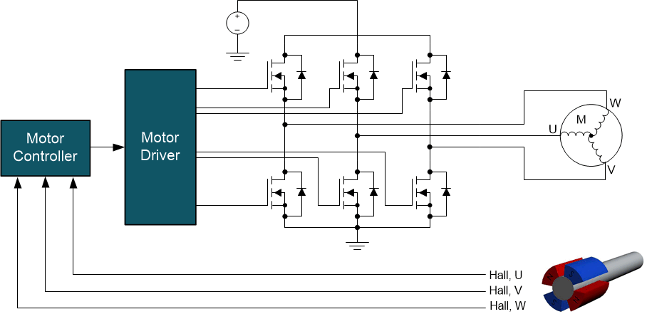 Figure 1-5 Closed-Loop System for BLDC Motor Control
Selecting the Right Hall Latch for BLDC Motor Commutation
The appropriate Hall latch to use for BLDC commutation is often selected based on the following specifications:
- Sensitivity: The sensitivity of the latch refers to the BOP and BRP specifications that cause the output of the latch to switch states when exposed to a magnet. The magnetic flux density seen by a latch is dependent on the size of the magnet, its magnetic material, and the distance from the magnet to the sensor. High-sensitivity latches have low BOP and BRP specifications, which can enable the motor to use smaller magnets to create a more compact motor design. For a given magnet, high sensitivity latches also enable a larger allowable magnet to Hall sensor distance than lower sensitivity latches.
- Current consumption: If the application is battery powered, the current consumption of the Hall position sensor should be low to maximize the lifetime of the battery.
- Operating voltage range: Since various systems have different available supply voltages, choose a Hall latch that operates within the voltage range of the system. If the available supply voltages of a system are all outside of the operating voltage range of the Hall position sensor, an additional voltage regulator device is needed to generate a voltage rail for powering the Hall position sensor.
- Open-drain vs push-pull output: Open-drain outputs are selected when it is desired to have the logic-high output voltage to be at a different voltage level than the VCC voltage of the Hall position sensor. Compared to open drain outputs, push-pull outputs do not require a pullup resistor, thereby reducing solution size.
- Frequency bandwidth: The device frequency bandwidth dictates the fastest changing magnetic field that can be detected and translated to the output, thereby determining how fast a motor can spin and still be detected by the Hall latch.
- Jitter: The jitter of a Hall latch is the variation seen in the output pulse width if the motor is spinning at a constant speed. Jitter introduces angle error in the measurement of the rotor position.
- Output Delay, Refresh Period: The output delay is defined as the time between the magnetic field crosses the BOP or BRP threshold and the time it takes for the output to reflect its new value. In sampled devices there is a refresh period, also referred to as sample rate, which is the period of time the device takes before a new magnetic sample is taken and used to update the output as necessary. Sampled devices tend to suffer from longer output delay times since the user must also account for the refresh period when the input is sampled as well as the output delay required to update the output.
- Temperature: Hall sensors need to operate at high temperatures if they are implemented in high-temperature motor applications.
- Size: The physical size of the device is important when designing compact motors. Battery-powered, handheld drills used in the medical field and in dentistry are examples of systems where a compact motor is beneficial. In this scenario, smaller motors reduce the overall weight of the system, reducing fatigue and stress on the end user while maintaining the same torque and battery life. For this reason, smaller Hall position sensors become extremely advantageous, as these can be placed strategically inside the motor casing without impacting the overall diameter of the motor design. To illustrate this point, consider the following package types — TO-92 and X2SON. The traditional TO-92 package (Figure 1-6) is most logically placed around the circumference of the rotor. For inner-rotor motor designs, this is typically not an issue, because the stator has enough room for the Hall sensors (stator not shown). The drawback with this approach is that it can lead to larger-diameter motor designs. In slotless BLDC motors, space is not available within the motor windings. Hall position sensors are optimally placed directly above the motor, on a PCB centered axially on the rotor shaft (Figure 1-7). This configuration shows that this package type does not impede the development of even smaller motor designs.
For more in-depth information on some of the latch specifications that were covered, see the Precision Labs video on Hall-effect latch specifications.
 Figure 1-6 Rotor Position Using TO-92
Hall Sensor
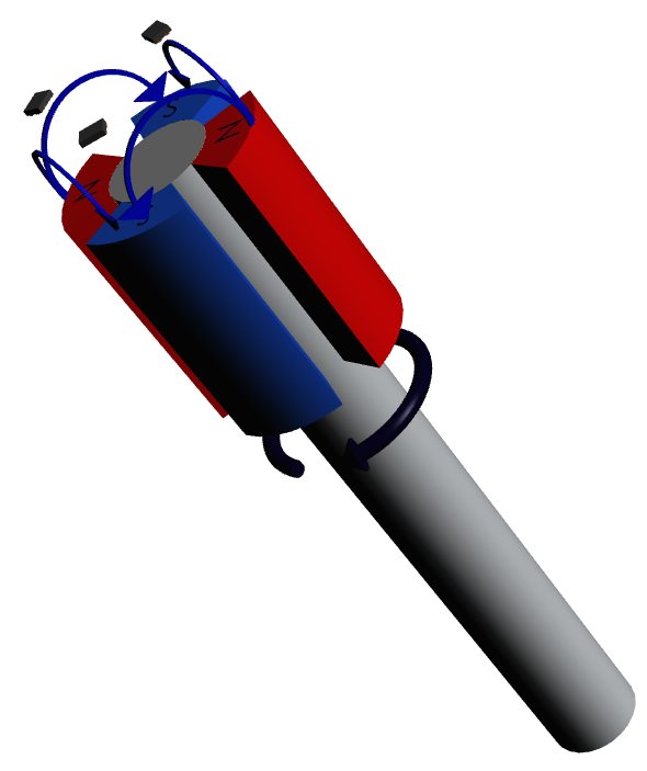 Figure 1-7 Rotor Position Using Surface
Mount Hall Sensor
Figure 1-7 Rotor Position Using Surface
Mount Hall SensorThe TMAG5115 is a family of high-performance digital Hall-effect latches designed with high performance in mind. The device offers low-jitter and low-output delay for systems that require high magnetic precision. Additionally, since motor systems can run the risk of generating voltage above the power supply, the TMAG5115 is capable of handling wide input voltage of 2.5 V up to an absolute maximum of 30 V. The wider voltage range can also allow users to run the device from the main supply line without the need of an additional regulator. The TMAG5115 also provides the highest frequency bandwidth available in TI’s Hall-effect latch portfolio, enabling the use of sensors in fast motor applications or in motors that have a high magnetic pole count.
The DRV5011 is a digital Hall-effect latch designed specifically for motors and other rotary systems. The device has an efficient, low-voltage architecture that operates from 2.5 V to 5.5 V. The device is offered in the standard SOT-23, as well as low-profile X2SON and DSBGA (WCSP) packages. The DSBGA package represents a 58% reduction in size when compared to the X2SON. Table 1-1 shows a comparison of the different packages.
| Package | Body Size |
|---|---|
| SOT-23 (3-pin) | 2.92 mm × 1.3 mm |
| X2SON (4-pin) | 1.1 mm × 1.4 mm |
| DSBGA (WCSP) (4-pin) | 0.8 mm × 0.8 mm |
The digital output of the device is a push-pull driver that requires no external pullup resistor, which enables even more compact systems.
Alternative Device Recommendations
Choose a Hall position sensor with specifications that meet the performance and functionality requirements of the system. For applications where space is not as constrained, the DRV5015 offers a good, high-bandwidth solution available in SOT-23. The DRV5015 also provides the highest sensitivity solution in TI’s product portfolio, and enables the use of smaller permanent motor magnets. Another popular product is the DRV5013, available in SOT-23 and TO92. The DRV5013 is a high-voltage solution that can operate up to 38-V VCC. Table 1-2 has links that provide more details on the specifications of these alternate devices:
| Device | Characteristic |
|---|---|
| DRV5013 | High voltage |
| DRV5015 | High sensitivity, low voltage |