SLVAEX8 October 2020 OPA4277-SP , TL1431-SP
Simulation Results
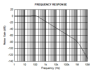
Op amp frequency response
The following figure shows the overall frequency response of the op amp circuit showing negligible gain peaking at the cutoff frequency.
Op amp stability
The following figure shows the bode plot of the op amp circuit. Phase margin is 64° and gain margin is 49 dB.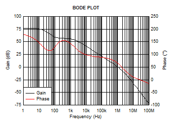
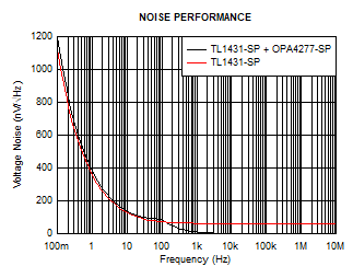
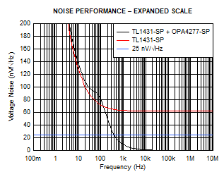
Noise performance
The following figures show the noise performance of the complete circuit with normal and expanded scales. The figures show that noise performance surpasses the design requirement limit of 25 nV/√Hz in the frequency range of 1 kHz to 10 MHz.