SLVAF37 January 2021 ATL431LI
2.1 Design Considerations for Optocoupler
Optocoupler is an electronic component that transfers electrical signals between two isolated circuits by using light. It is common to find commercial products consist of an infrared emitting diode, optically coupled to a phototransistor detector. Basically the light from the diode acts like a base current to the transistor and the amount of light can be controlled by bias current into the diode.
Here we need to note one premise that the phototransistor should work in a linear region for normal condition wherein there is only a small change in the level of Vout. That means just a few tens of, or hundreds of change of u-volt or u-Amps in diode side can make the variation to the VCE. Extreme conditions such as high overvoltage, deep undershoot would require opto to work in saturation or cut-off region but, we assume that controller protects those extreme situation so no cases to consider into.
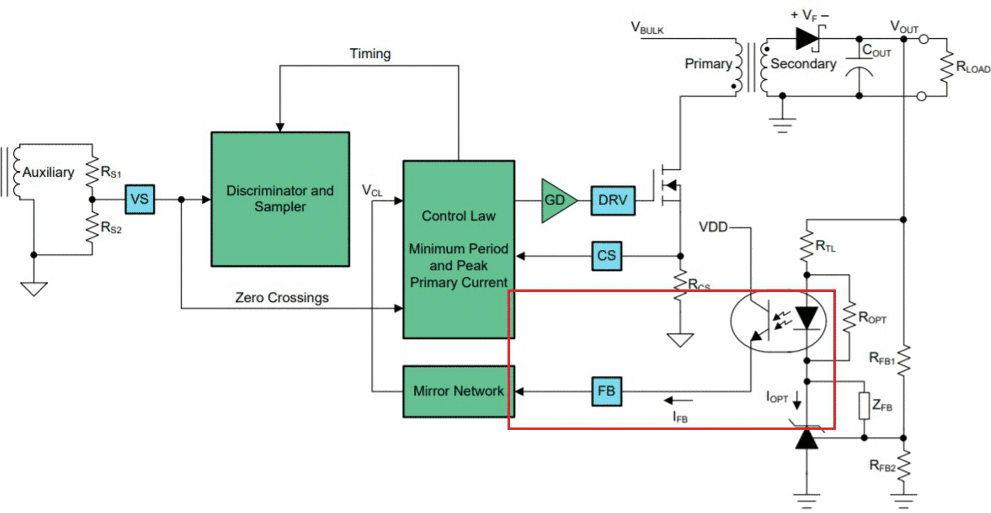
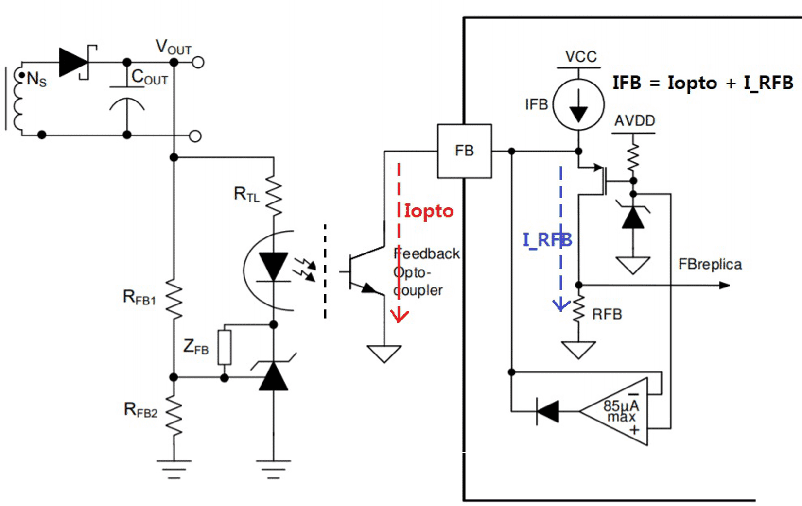
Step 1: Check the primary side controller’s FB configuration. Maximum FB current.
 Figure 2-1 Example of UCC28740 (Low Side
Current Sinking)
  Figure 2-2 Example of UCC25640x (High
Side Current Sourcing)
Figure 2-2 Example of UCC25640x (High
Side Current Sourcing)Step 2: High and Narrow variation CTR is essential.
As we focus on linear operation, a tight CTR will correspond to a smaller variation. Also, for higher design accuracy, designers should take ambient temperature, life cycle into account. Each vendor provides the information by the curve such as Relative CTR vs Temp, Operating hour in the data sheet.
Step 3: Users should understand how to bias optocoupler.
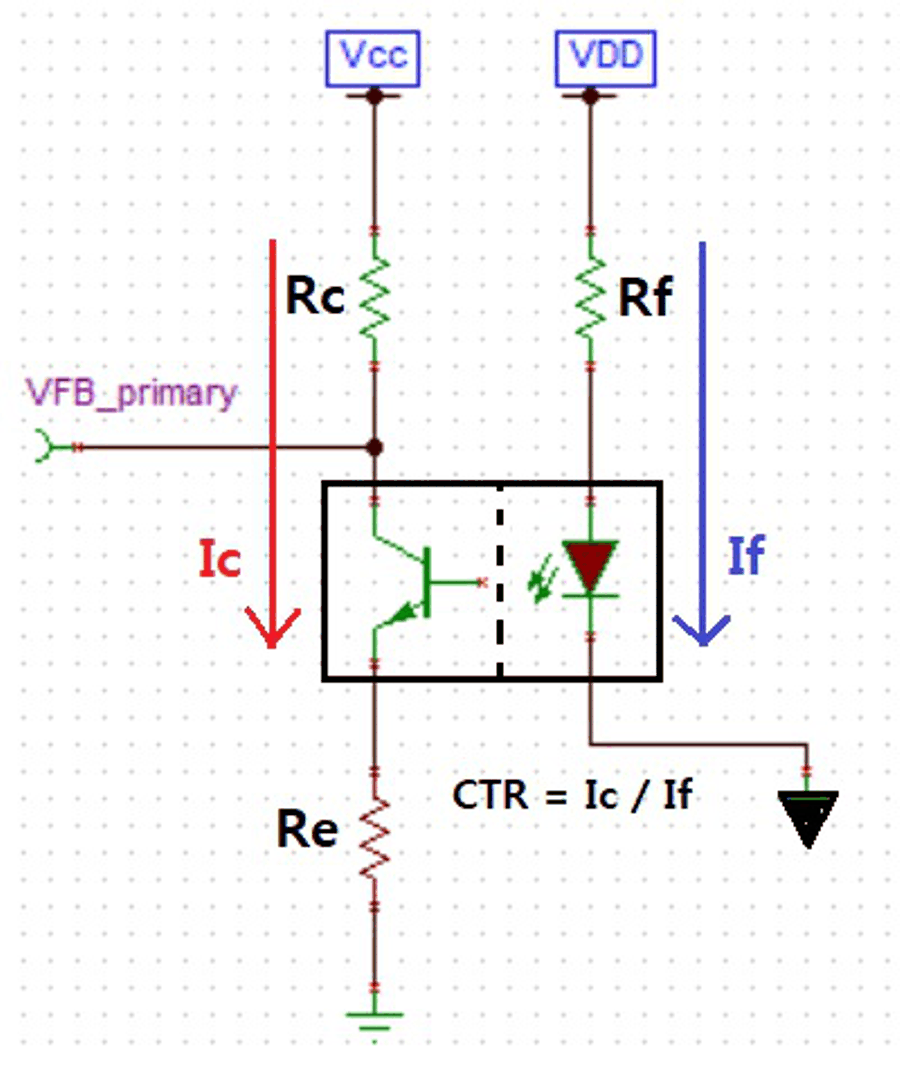
There are multiple, widely 4 variations configuration to bias optocoupler. As seen at Step1, we can choose the way depending on controller’s requirement and should be able to analyze the circuit. We are not going to look into, but note that it is very easy KVL analysis based on the fact that the base of the photoTR is open (electrically isolated) and it makes the collector current and emitter current equal. Once we determine VDD, we set a proper diode current (IF) and can compute corresponding collector current (Ic).
 Figure 2-3 One Example of Biasing
Optocoupler