SLVAFA2 February 2022 TPS1HC100-Q1
4 Overview of Embedded System
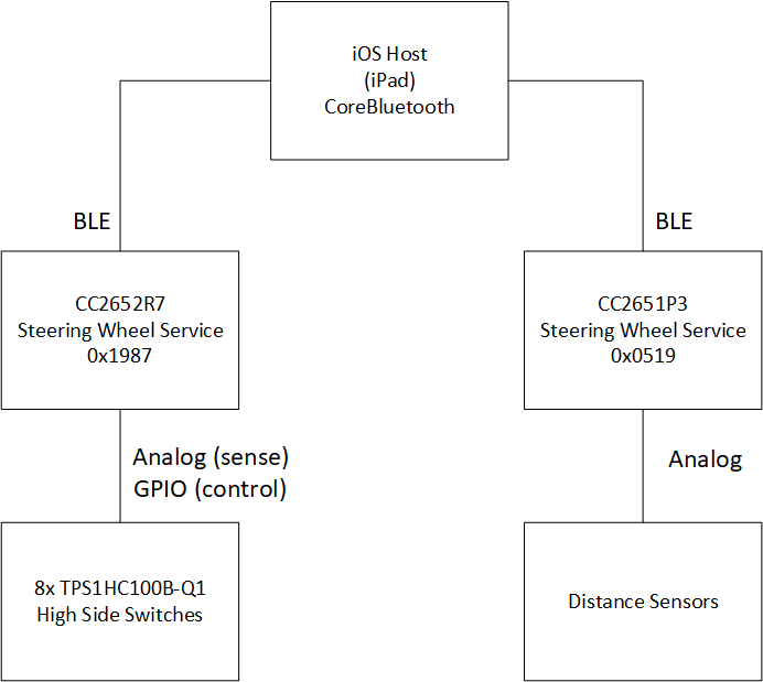
In the reference design system, a couple if different wireless microcontrollers are used in peripheral mode. A CC2652R7 ARM Cortex-M4F microcontroller is used on the steering wheel to control and configure the series of TPS1HC100B-Q1 high side switches. The CC2652R7 advertises a set of BLE services/characteristics for the host the manipulate and configure. For the distance sensors attached to the model car, a scaled down CC2651P3 ARM Cortex-M4F microcontroller is used to continuously measure the current of the array of sensors and report the reading values to a BLE host. The BLE host in this system is a standard Apple iPad® running a simple Swift application with a CoreBluetooth backend. The iOS application acts as the central brain of the system by reading the sensor values from the CC2651P3, performing analysis/processing to determine how close an object is, and then alerting the CC2652R7 microcontroller on the steering wheel in the event that an alert event should occur. A block diagram of the embedded portions of this system is shown in Figure 4-1.
 Figure 4-1 Software Block Diagram (iOS
Host)
Figure 4-1 Software Block Diagram (iOS
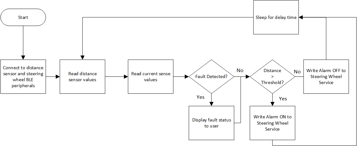
Host)Additionally, a software flowchart of the distance detection can be seen below in Figure 4-2. This flowchart is from the perspective of the iOS host controlling both the CC2652R7 and CC2651P3 microcontroller.
 Figure 4-2 Flowchart (Distance
Detection)
Figure 4-2 Flowchart (Distance
Detection)The CC2652R7 attached to the steering wheel advertises over BLE the following service with the listed characteristics as shown in Table 4-1.
| Characteristic | UUID (Hex) | Format | Description |
|---|---|---|---|
| Sensor Alarm | 0xFFF1 | uint8_t | Value to enable/disable driving of alarm loads. |
| Sense Values | 0xFFF2 | uint16_t [8] | Raw ADC conversion results of sense current |
| Gyrometer Values | 0xFFF3 | uint16_t [6] | Raw gyrometer values from BOOSTXL-SENSORS |
| Heater Enable | 0xFFF4 | uint8_t | Enable/disable steering wheel heater |
The CC2651P3 attached to the model car advertises the services/characteristics shown in Table 4-2.
| Characteristic | UUID (Hex) | Format | Description |
|---|---|---|---|
| Sensor Distance #1 | 0xFFF1 | uint16_t | Left distance sensor |
| Sensor Distance #2 | 0xFFF2 | uint16_t | Center distance sensor |
| Sensor Distance #3 | 0xFFF3 | uint16_t | Right distance sensor |
The CC2652R7 BLE microcontroller embedded in the steering wheel controls all aspects of the array of TPS1HC100B-Q1 high side switches connected to the system. The tasks that the CC2652R7 includes the following:
- Enabling/disabling power to the automotive loads on distance events
- Continuously measuring the load current of attached loads
- Advertise configuration BLE services and characteristics
- Manage attached gyrometer from BOOSTXL-SENSORS BoosterPack
- Monitor fault status of the attached TPS1HC100B-Q1 automotive loads (overcurrent, open load, and so on.)
As the CC2652R7 is a microcontroller designed for low-scale embedded systems, no algorithm intensive computations or CPU heavy calculations are performed on the CC2652R7 itself. Instead, the iOS host is used to perform all the heavy lifting with respect to the data processing and distance detection. The CC2652R7, instead, takes the read values from the TPS1HC100B-Q1's current sense and places them in a buffer for the iOS host to read. To do this efficiently for all eight TPS1HC100B-Q1 devices attached to the system, a sequence of channels conversion is performed using the ADC_convertChain function from the SimpleLink SDK drivers package. This conversion can be seen in the snippet below:
adc[0] = ADC_open(SNS1, ¶ms);
adc[1] = ADC_open(SNS2, ¶ms);
adc[2] = ADC_open(SNS3, ¶ms);
adc[3] = ADC_open(SNS4, ¶ms);
adc[4] = ADC_open(SNS5, ¶ms);
adc[5] = ADC_open(SNS6, ¶ms);
adc[6] = ADC_open(SNS7, ¶ms);
adc[7] = ADC_open(SNS8, ¶ms);
while(1)
{
ADC_convertChain(adc, sampleBuffer, 8);
SteeringWheelProfile_SetParameter(STEERINGWHEEL_CHAR2, 16,
&sampleBuffer);
Task_sleep(1000);
}The iOS software running on the iPad will periodically poll the value in STEERINGWHEEL_CHAR2, parse out the various load currents represented by ADC conversion results, and then display them on the iPad frontend for the user to see.
The distance detection itself is done on the iOS host using a simple threshold algorithm. Each sensor has a corresponding threshold value associated with it for far, medium, and close. If the value read from the CC2651P3 crosses any of these threshold, a value of 3, 2, or 1 is written to the STEERINGWHEEL_CHAR1 characteristic of the CC2652R7 MCU in the steering wheel. These values correspond to the intensity at which the alert should trigger on the steering wheel system. A close value, for example, corresponds to a collision eminent event where the loads/alarms would trigger on the steering wheel at full intensity. A code snippet of the iOS code that handles the thresholding follows:
            if(characteristic == leftChar)
            {
                let intValue = (UInt16(data[1]) << 8) | UInt16(data[0])

                leftValues[frontPos] = intValue
                leftPos+=1

                if(leftPos == NUM_DIST_VALS)
                {
                    leftPos = 0
                    leftPasssed = true
                }

                var curSum: Int = 0
                for curVal in leftValues
                {
                    curSum += Int(curVal)
                }

                let curAvg = curSum / NUM_DIST_VALS

                if(curAvg >= LEFT_THRESH3)
                {
                    leftLevel = 3
                }
                else if(curAvg >= LEFT_THRESH2)
                {
                    leftLevel = 2
                }
                else if(curAvg >= LEFT_THRESH1)
                {
                    leftLevel = 1
                }
                else
                {
                    leftLevel = 0
                }
            }
In this snippet, the left sensor is compared to a set of threshold values from far, medium, and close distances. Depending on the corresponding level, an integer value is assigned to the leftLevel variable. This variable is later combined into a single 8-bit integer and written to the alarm characteristic of the steering wheel if an alarm is triggered. Also note that the distance algorithm implements an elementary form of averaging/integration over NUM_DIST_VALS number of values (default five). This is to avoid any false triggers resulting from the sensitivity of the distance sensors. The actual writing of alarm is done using the standard CoreBluetooth APIs shown in the following wrapper function:
    func writeAlarm(command: UInt8)
    {
        if((autoPeripheral != nil) && (autoPeripheral.state == .connected))
        {
            autoPeripheral.writeValue(Data([command]),
                                      for: autoAlarmChar, type: .withResponse)

        }
    }