SLVAFJ9 March 2023 TPSF12C1 , TPSF12C1-Q1 , TPSF12C3 , TPSF12C3-Q1
- Abstract
- 1 Table of Contents
- Trademarks
- 2 Introduction
- 3 EMI Frequency Ranges
- 4 Passive EMI Filters for High-Power, Grid-Tied Applications
- 5 Active EMI Filters
- 6 Generalized AEF Circuits
- 7 Selection of the CM Active Filter Circuit
- 8 The Concept of Capacitive Amplification
- 9 Practical AEF Implementations
- 10Practical Results
- 11Summary
- 12References
8 The Concept of Capacitive Amplification
An AEF circuit for CM noise mitigation either amplifies the apparent inductance of a CM choke or the apparent capacitance of a Y-capacitor over the frequency range of interest. A VSCI AEF configured for CM attenuation uses an amplifier stage as a capacitive multiplier of the injection capacitor, CINJ. It is this higher value of active capacitance that supports lower values for the CM chokes to achieve a target attenuation.
Looking at Figure 7-1, Equation 1 shows that the injection capacitance is effectively multiplied by GAEF, the CM voltage gain from the power lines to the amplifier output:
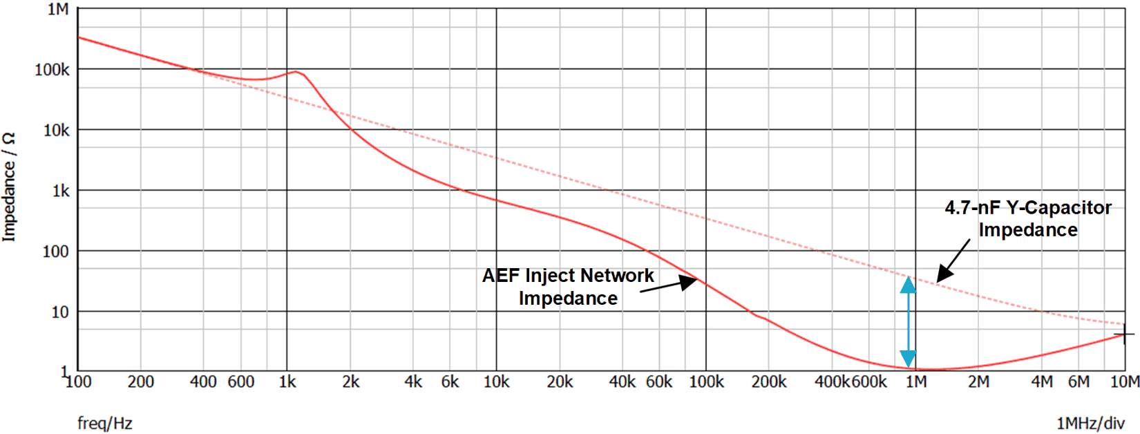
Figure 8-1 shows a simulated plot of an injection network impedance when a FB-VSCI AEF circuit is enabled and disabled. The lower impedance above 2 kHz (and especially above 100 kHz) is caused by the capacitive amplification by the active circuit of a 4.7-nF injection capacitor and its associated damping network.
 Figure 8-1 Example of Inject Branch
Impedance ZINJ With AEF Enabled vs. a Conventional Y-Capacitor,
Showing the Boosted Equivalent Capacitance at Higher Frequencies by Active
Feedback Action