SLVAFR6 January 2024 LM5067
3 Testing and Verification
When the dynamic variation range of VS-VEE is -9V to -63.5V, the voltage swing of UVLO Pin can be expressed as Equation 5.
When VS = 5V, the theoretical values of the UVLOMAX is 12.39V.
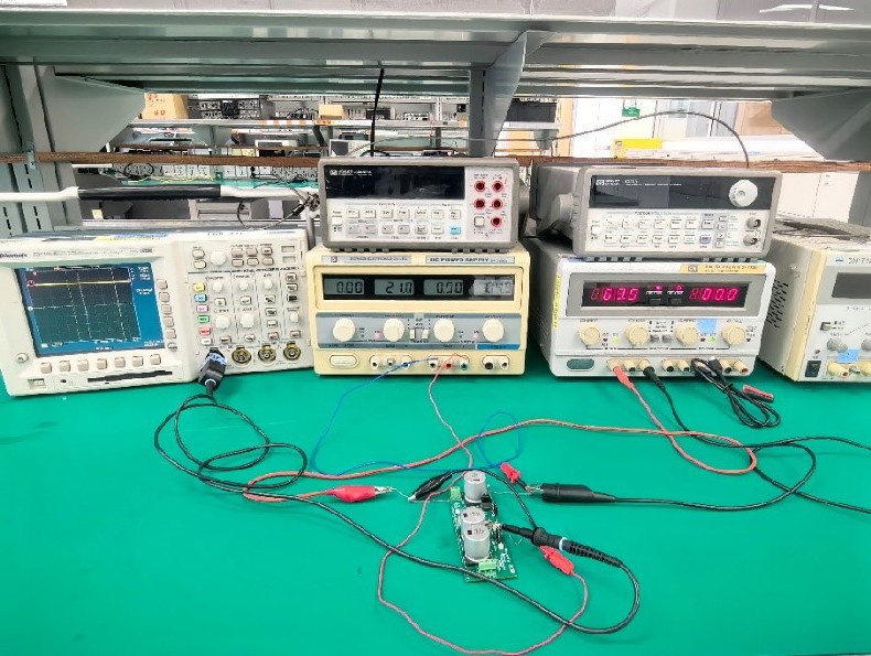
The actual test conditions are shown in Figure 3-1, and the setting is VS = 4.9V and VEE = 63.5V.
 Figure 3-1 Actual Test Conditions
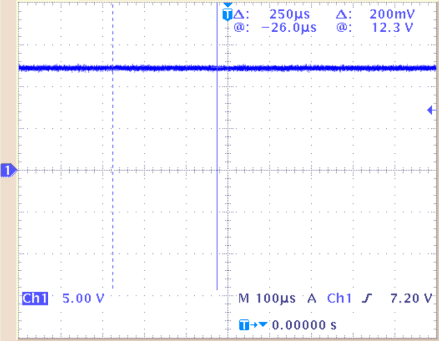
The test results are shown in Figure 3-2, and the measured UVLO is 12.3V, which is in line with the theoretical expectation.
 Figure 3-2 Measured Voltage at UVLO
Pin
Figure 3-2 Measured Voltage at UVLO
PinAccording to this method, the LM5067 can be made to work normally in a larger dynamic voltage range by applying an external power supply VS, which solves the problem of the LM5067 under the traditional single negative power supply, eliminates the limit of the dynamic output voltage range of the chip caused by UVLO pin voltage limit. For further protection of the UVLO Pin pin, A TVS or Zener diode can be added between VEE pin and VIN pin for voltage clamping.