SLVUAA6B November 2014 – October 2022 TPS65218 , TPS6521815 , TPS6521825 , TPS6521835 , TPS6521845 , TPS65218D0
7.2 Using the TPS65218 GUI
Detailed information regarding the usage of the IPG-UI can also be found in the IPG-UI User's Guide. A brief overview is provided here for reference.
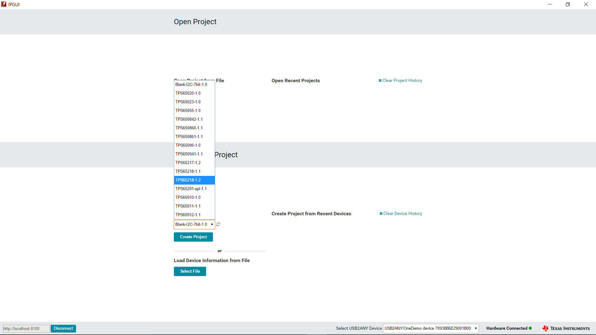
The proper device must first be selected from the "Select Devices" drop-down menu.
 Figure 7-1 GUI front
Page
Figure 7-1 GUI front
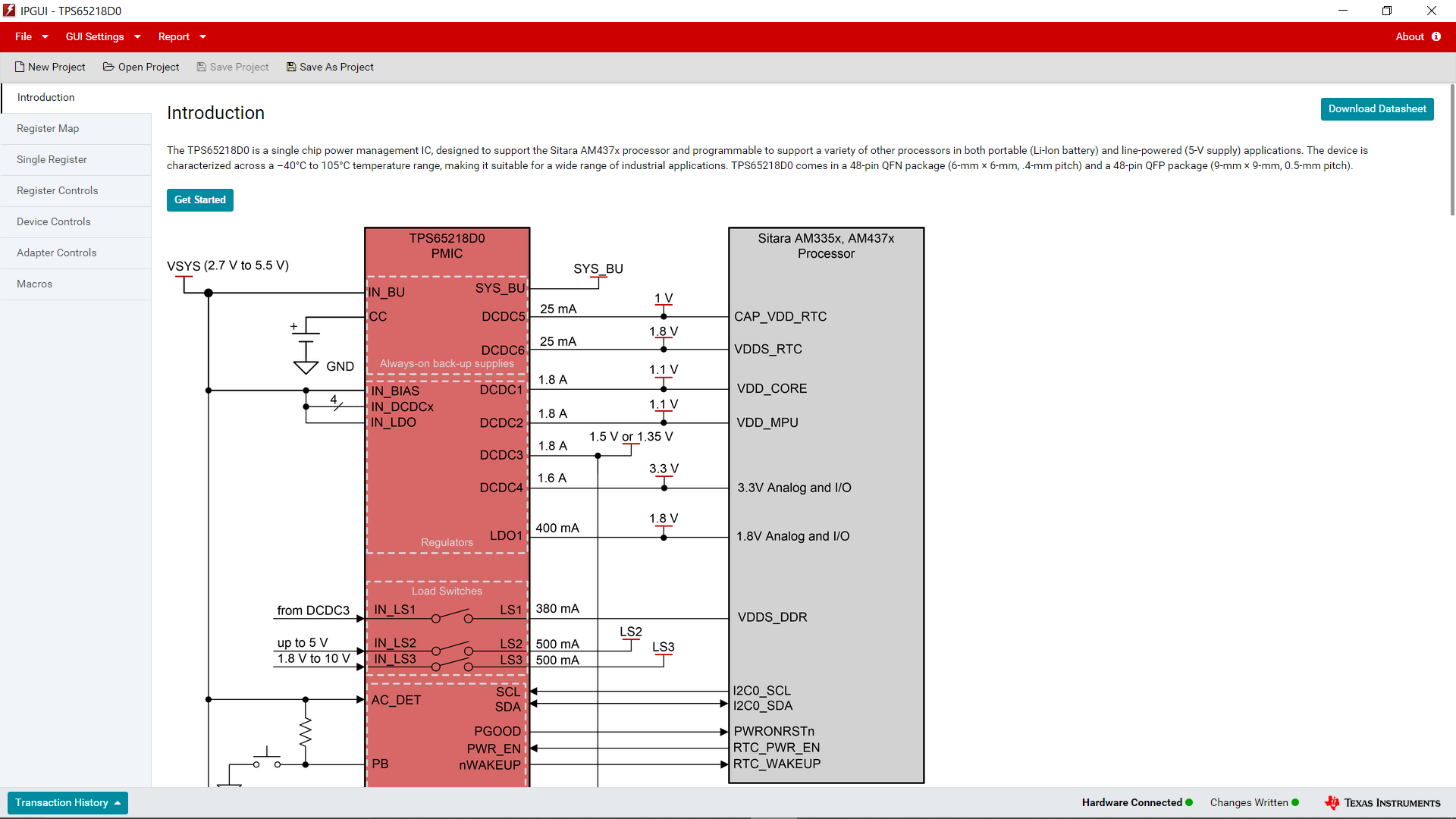
PageFrom there, the next screen is the device introduction page, which includes a brief overview as well as the functional block diagram for the device.
 Figure 7-2 GUI
Device Introduction
Figure 7-2 GUI
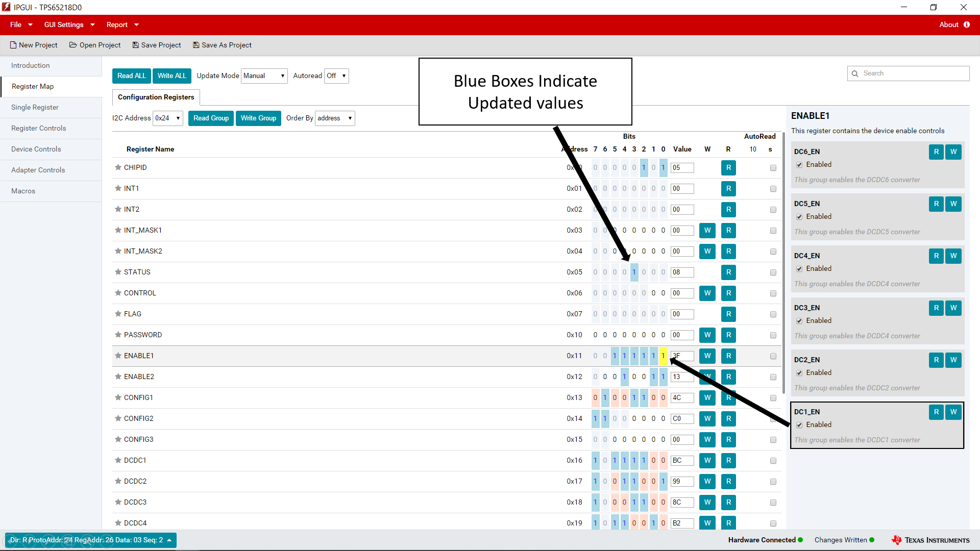
Device IntroductionFinally, clicking on "Get Started" or on "Register Map" takes you to the I2C controls for the device sorted by register address.
 Figure 7-3 GUI
Register Map
Figure 7-3 GUI
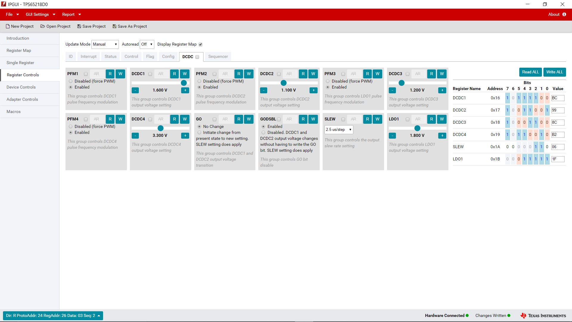
Register MapAlternatively, the part can be controlled using the "Register Controls" tab to sort by functionality rather than by I2C address location.
 Figure 7-4 GUI
Register Controls
Figure 7-4 GUI
Register ControlsWith this information, it is possible to begin evaluating the TPS65218 device.