SLVUB95C December 2017 – August 2018
6.1 Jumpers
Descriptions for the jumpers are provided in the following list:
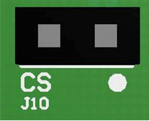 Figure 8. CS Receptacle (J10)
 - CS (J10) is the current limit setting. CS connects a resistor to GND for current-limit setting. This receptacle is meant for easy implementation of axial-lead through-hole resistors. Otherwise, R4 can be used for substitution of surface-mount resistors.
- ADV (J8) is the lead angle setting. ADV connects a resistor to GND for lead angle setting. This receptacle is meant for easy implementation of axial-lead through-hole resistors. Otherwise, R2 can be used for substitution of surface-mount resistors.
- RMP (J9) is the acceleration ramp-rate control setting. RMP connects a resistor to GND for setting the acceleration ramp-rate control. This receptacle is meant for easy implementation of axial-lead through-hole resistors. Otherwise, R3 can be used for substitution of surface-mount resistors.
- Select (J3) is used to configure motor speed-control resources for the PWM pin. Set the PWM jumper to PWMIN for sending a PWM signal to the PWM pin to control motor speed. See Figure 4 for more details. Set the PWM jumper to Analog with J2 connected for using potentiometer (R5) to control motor speed. See Figure 3 for more details.
- J7 and J11 Connections are placeholders for an I2C interface, so they can be ignored.
- Potentiometer Power (J2) provides voltage from the V1P8 pin of the DRV10974 device to power the potentiometer. This header must be jumpered to use the potentiometer.
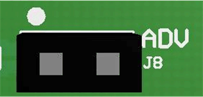 Figure 9. ADV Receptacle (J8)
 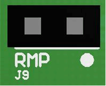 Figure 10. RMP Receptacle (J9)
 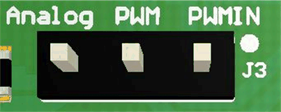 Figure 11. Speed Command Input Select Header (J3)
 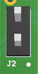 Figure 12. Potentiometer Power Header (J2)