SLVUBH1 September 2018
1 What You Get
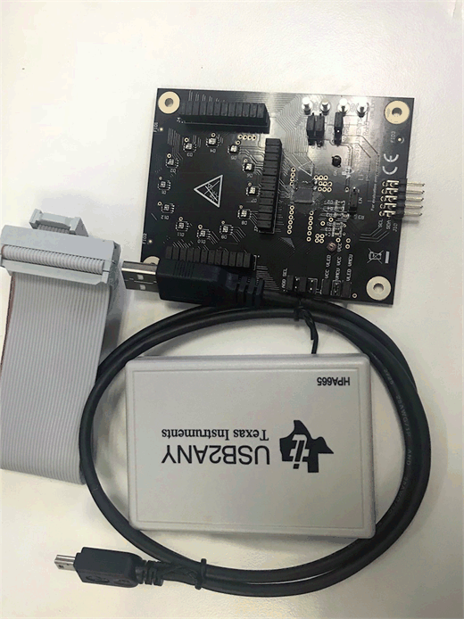
The LP5036EVM kit (Figure 1) contains:.
- USB2ANY
- Ribbon cable
- USB cable
- LP5036EVM
 Figure 1. LP5036EVM Kit
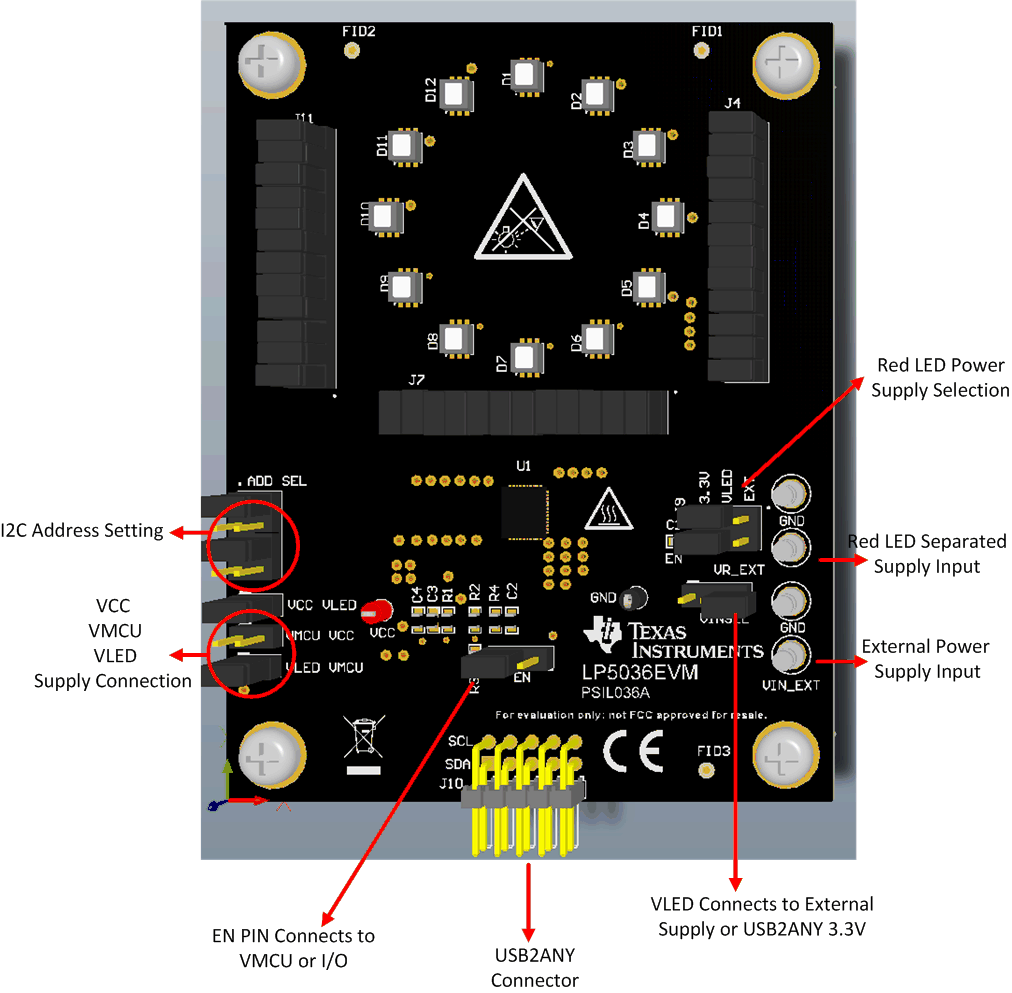
 Figure 2 shows the key connectors used to operate LP5036EVM.
 Figure 2. LP5036EVM Key Connectors
 Table 1. LP5036EVM Parameters
| PARAMETER | RANGE |
|---|---|
| VCC | 3 V–5.5 V |
| VLED | 3 V–5.5 V |
| VMCU | 1.8 V, 3.3 V, 5 V |
| Channel current | 35 mA (maximum) |
Note: Channel current is set at 20 mA when the LED supply voltage is 5 V. Although the LP5036 device can withstand 6-V maximum LED supply voltage with 35 mA per channel, make sure that the PCB thermal performance can meet the power dissipation requirement, because increased LED supply voltage increases channel output current.