SLVUCD8 February 2022
5 Schematics
For TPS7H5005EVM schematics, see Figure 5-1 through Figure 5-4.
For TPS7H5006EVM schematics, see Figure 5-5 through Figure 5-8.
For TPS7H5007EVM schematics, see Figure 5-9 through Figure 5-12.
For TPS7H5008EVM schematics, see Figure 5-13 through Figure 5-16.
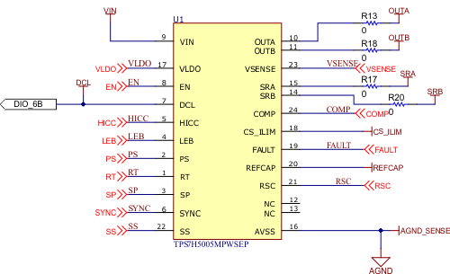 Figure 5-1 TPS7H5005EVM Schematic (Page
1)
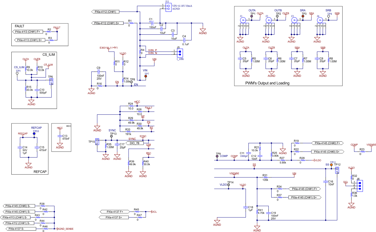 Figure 5-2 TPS7H5005EVM Schematic (Page 2)
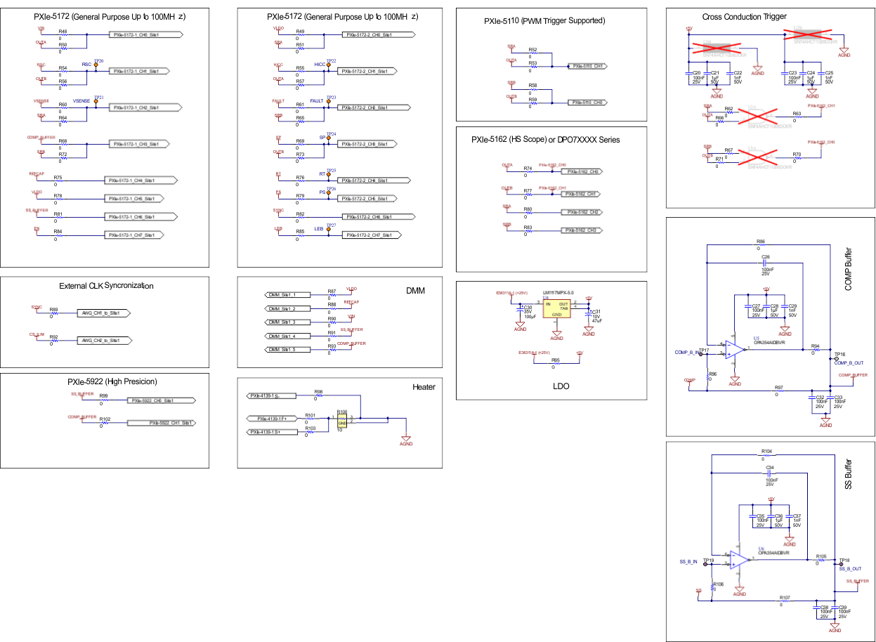 Figure 5-3 TPS7H5005EVM Schematic (Page 3)
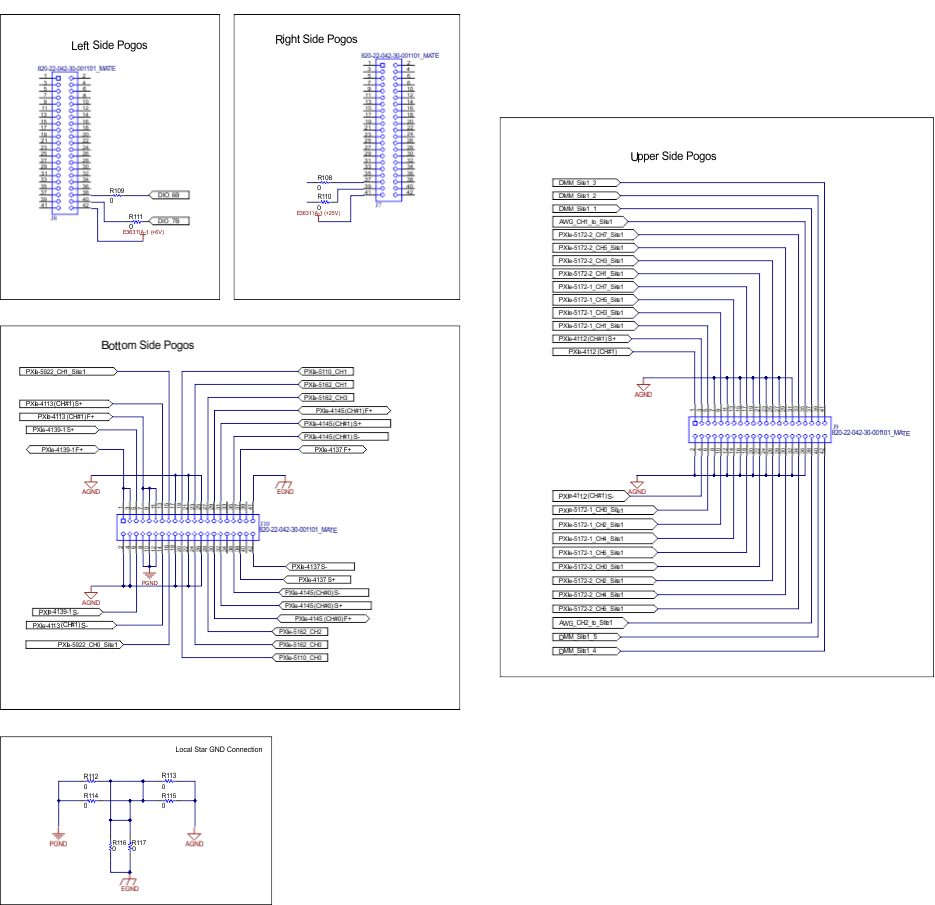 Figure 5-4 TPS7H5005EVM Schematic (Page 4)
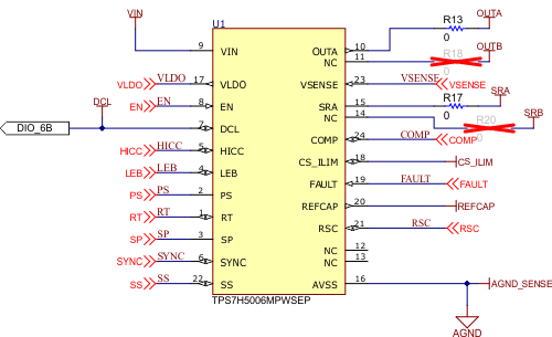 Figure 5-5 TPS7H5006EVM Schematic (Page
1)
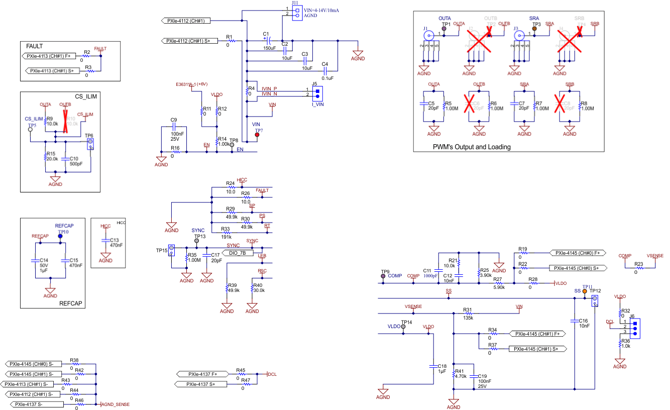 Figure 5-6 TPS7H5006EVM Schematic (Page 2)
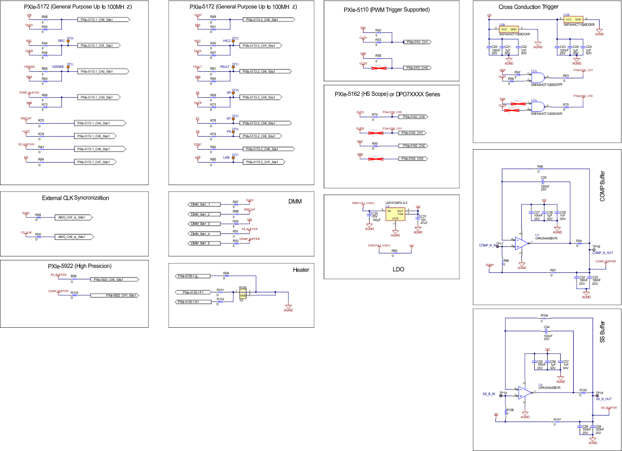 Figure 5-7 TPS7H5006EVM Schematic (Page 3)
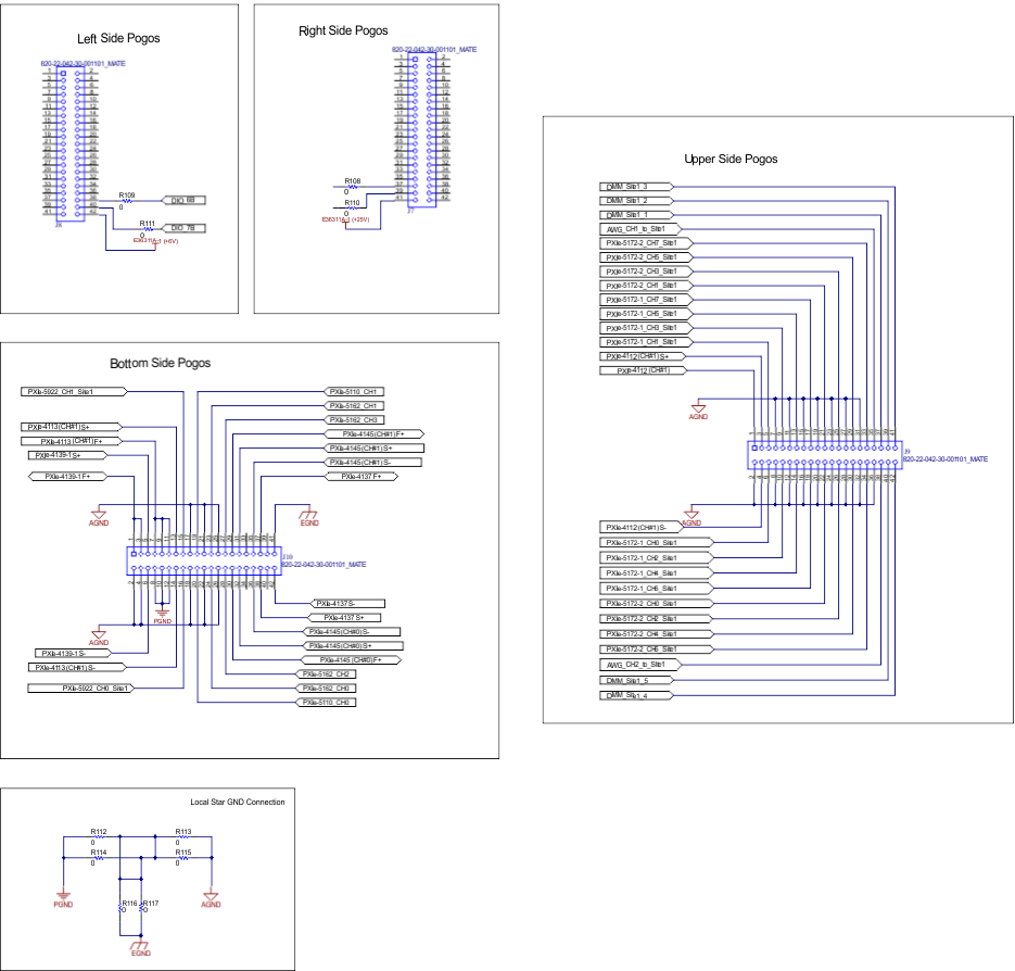 Figure 5-8 TPS7H5006EVM Schematic (Page 4)
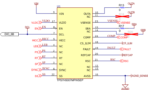 Figure 5-9 TPS7H5007EVM Schematic (Page
1)
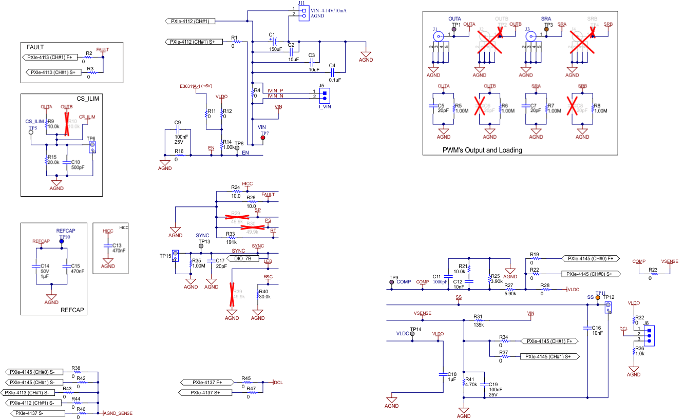 Figure 5-10 TPS7H5007EVM Schematic (Page 2)
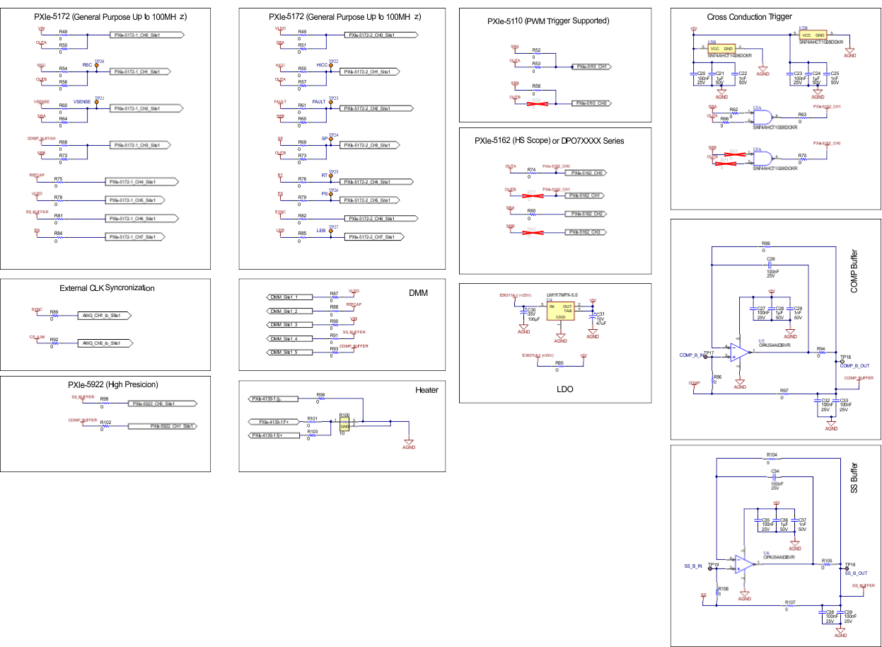 Figure 5-11 TPS7H5007EVM Schematic (Page 3)
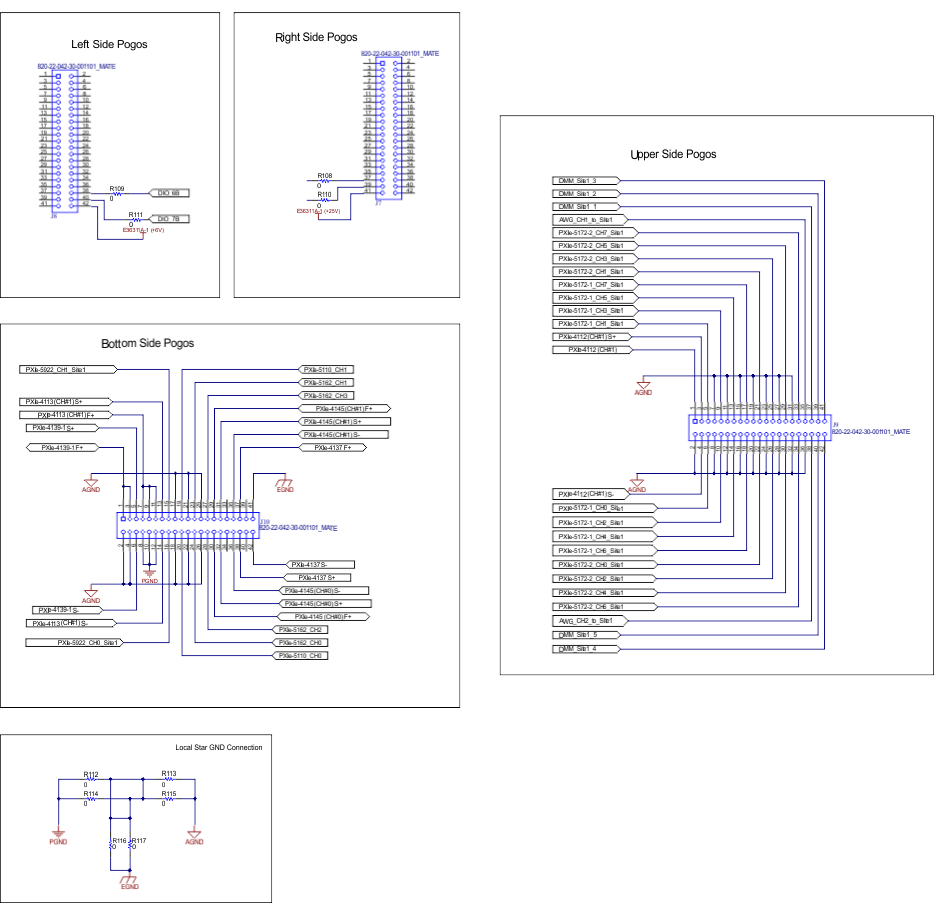 Figure 5-12 TPS7H5007EVM Schematic (Page 4)
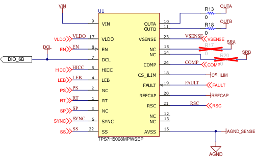 Figure 5-13 TPS7H5008EVM Schematic (Page
1)
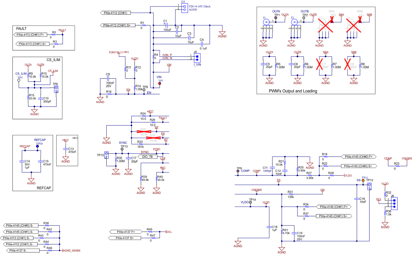 Figure 5-14 TPS7H5008EVM Schematic (Page 2)
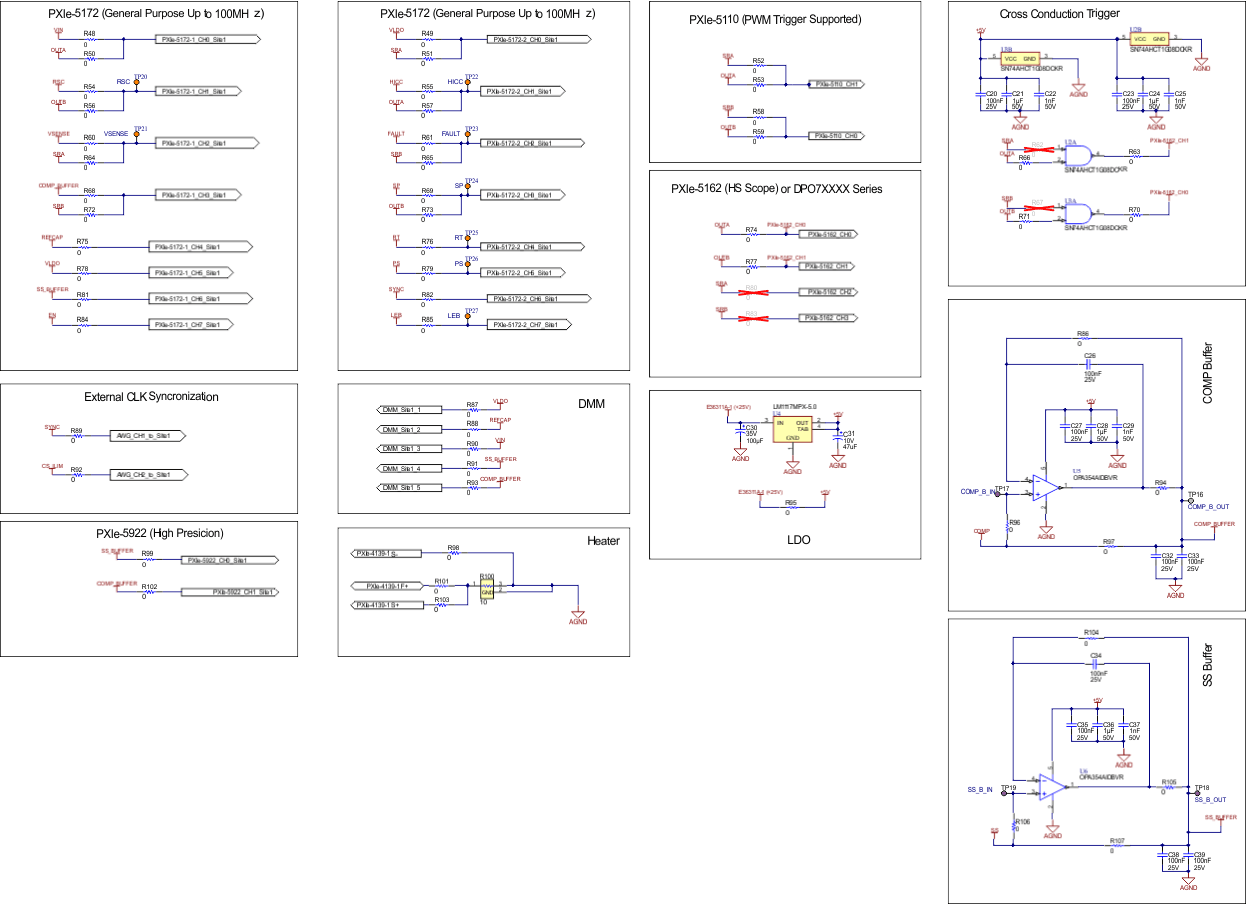 Figure 5-15 TPS7H5008EVM Schematic (Page 3)
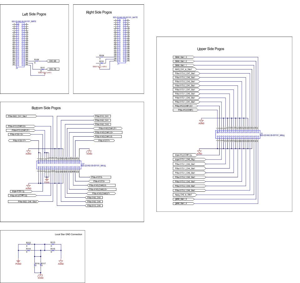 Figure 5-16 TPS7H5008EVM Schematic (Page 4)