SLYA058 June 2022 DRV5021 , DRV5032 , DRV5033 , TMAG5123 , TMAG5124 , TMAG5170 , TMAG5273 , TMAG5328
2.2 Rotational Sensing With 3D Hall-Effect Sensors
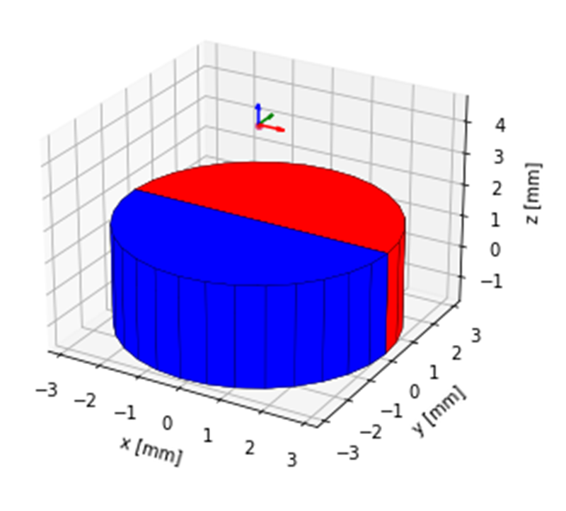
In a system that needs a higher resolution of the rotational angle, a single 3D Hall sensor can be used to detect the angle of the magnet. Since this device only requires one device, the best placement for the sensor is directly on top of the magnet so the rotation only happens on the Z axis of the sensor.
 Figure 2-5 3D Hall-Effect Sensor
Placement Example
Figure 2-5 3D Hall-Effect Sensor
Placement ExampleThe sensor and the magnet are perfectly aligned so only the X and Y portions of the magnetic field are varying while the magnet rotates.
As shown in Figure 2-6, only two of the magnetic field axis are needed to determine the angle of the magnet so the third axis is free to implement tamper detection or to gather additional information on the device status. To determine the angle of the magnet, the data can be processed with an MCU. However, devices like the TMAG5273 and TMAG5170 have an integrated CORDIC algorithm that reports the angle as a register value so no additional calculations are needed from the MCU. If there is a shift or offset in the magnet and sensor alignment, then the Z axis of the magnetic field will change. If the magnet is still aligned with the axis of rotation but no longer aligned with the sensor, then the Z axis starts to change in a sinusoidal pattern.
Having the Z axis magnetic field vary like this indicates that the magnet is still rotating about its center, but the magnet is no longer aligned with the sensor. Another offset that can occur is having the magnet no longer on the axis of rotation. As long as the sensor is still in line with the axis of rotation, this causes the Z axis magnetic field to become a constant.
Knowing the expected results from these two different offset types, the Z axis of the magnetic field can be used for predictive maintenance of the system. If these offsets appear while the product is in use, it means that something has shifted and may need to be realigned. The offset in the Z axis could also be used to determine if an external magnet is being applied to the system. If this is the case, there could also be an impact to the expected data of the X and Y magnetic field axis.
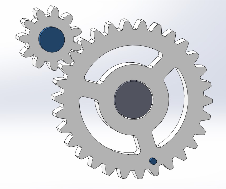
Many times, the magnet for this implementation cannot be placed directly on the center shaft or motor. In that case, a gear can be used to offset the magnet rotation and change the resolution of the magnet angle to the deadbolt position. By using a gear ratio that allows the magnet to spin more than the center shaft, a larger angle variation will occur for the motion of the deadbolt. This can be used to gain increased resolution on the position of the deadbolt if desired. An example of this is shown in Figure 2-9.
 Figure 2-9 Magnet on Gear Example
This example has the offset gear that rotates a magnet directly above a linear Hall sensor as well as a magnet that moves along the outer edge of the larger gear. The smaller magnet moves in an arced path that works with the switch implementation previously discussed. This is just one way to implement these magnets for this application. Since the magnet is the main care about, the method of mechanical motion can be changed or adjusted as needed to fit the application.