SLYT800B december 2020 – december 2020 LM25180 , LM25183 , LM25184 , LM5180 , LM5181
5 Output Capacitor Sizing for Small-signal Stability
From Figure 6, the loop gain generally presents as a slope of –20 dB per decade up to and beyond fC, simplifying the determination of required output capacitance. From Equation 7, Equation 9 gives a simplified loop gain expression in DCM:
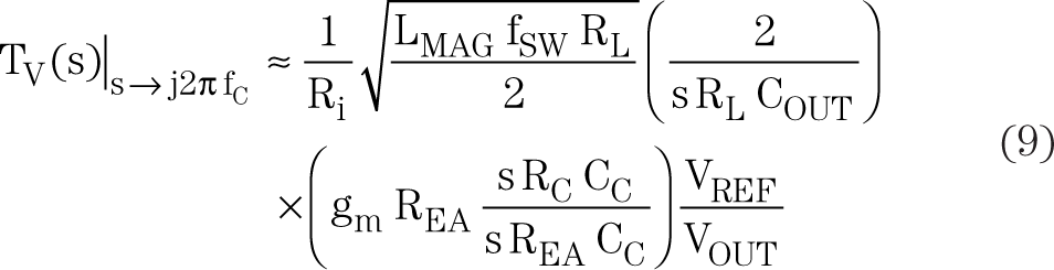
where RC and CC denote the compensation resistance and capacitance, respectively.
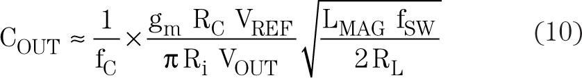
Equation 9 further simplifies to yield an expression for COUT based on a target crossover frequency at unity gain (Equation 10):
 and 42 v (Solid Lines, DCM)") Figure 6 Simulated Bode Plots at Input
Voltages of 14 v (Dashed Lines, BCM) and 42 v (Solid Lines, DCM)
Figure 6 Simulated Bode Plots at Input
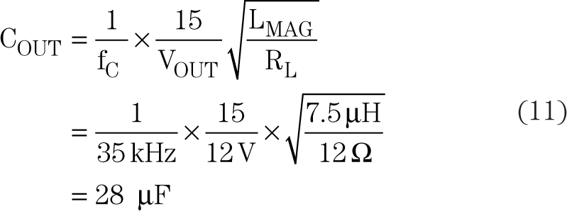
Voltages of 14 v (Dashed Lines, BCM) and 42 v (Solid Lines, DCM)Using parameters from the LM25184 circuit shown in Figure 1, Equation 11 gives the output capacitance for a target crossover frequency of 35 kHz (10% of the switching frequency):
overestimation given the attenuating contributions from the PSR sample-and-hold and the current-mode control high-frequency pole (although offset by the RHPZ gain) that may exist at a high fC. The result also aligns with a generally satisfactory load transient response.