SLYT823 March 2022 LM25149-Q1
3 AEF damping
Because of thermal variation or switching jitter, power converters may generate noise at frequencies lower than their switching frequencies, which is referred to as low-frequency disturbance in this article. For the AEF in Figure 2-1(b), Equation 1 expresses its equivalent impedance as:
where Zop and Gop_amp are the output impedance and voltage gain from the sensing node to the output of the op amp and ZC_inj is the impedance of the injection capacitor [2].
According to Equation 1, the equivalent impedance of the AEF in Figure 2-1(b) is capacitive at low frequency. As a result, the AEF can resonate with differential mode inductor L at low frequencies, such as between 10 kHz to 100 kHz. Given the resonance, the low-frequency disturbance could lead to a large op-amp output voltage and output current. As the op amp has limited output swing and output current capability, the op amp could enter the nonlinear region or even become saturated, potentially affecting AEF performance and causing the AEF to inject additional noise into the system.
Dealing with this problem requires damping the resonance. Figure 3-1 shows two damping methods by making the AEF less capacitive at the resonant frequency. In Figure 3-1(a), a damping resistor, Rdamp, is inserted in the injection path. In this way, the larger Rdamp is, the better the resonance damping. With the damping network inserted, however, Equation 2 expresses the equivalent impedance of the AEF as:
where Zdamp is the impedance of the damping network [2].
A large Rdamp would increase Zeq_AEF, thus affecting the performance of the AEF. So this damping method mainly works for high-frequency switching converters, such as 2 MHz. To effectively damp the resonance, the quality factor should be around or below 1. To get the quality factor near 1, calculate Rdamp according to Equation 3:
To improve the performance of the AEF shown in Figure 3-1(a), place a capacitor, Cdamp, in parallel with the damping resistor, Rdamp, as shown in Figure 3-1(b). At the resonant frequency, resistor Rdamp dominates the impedance of the damping network to damp the resonance. At high frequencies where the AEF needs to attenuate noise, capacitor Cdamp dominates the impedance of the damping network, thereby ensuring the performance of the AEF. Following a similar optimization method as described in [4], Equation 4 and Equation 5 express a good combination of Rdamp and Cdamp for the resonance damping:
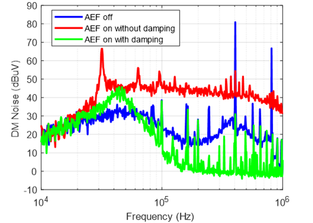
Figure 3-2 shows the spectrum test results from 10 kHz to 1 MHz of a 400-kHz buck converter with AEF off, with AEF on but no damping, and with AEF on and with resistor-capacitor parallel damping where Rdamp and Cdamp are selected based on Equation 4 and Equation 5. In Figure 4-1, without damping, there is a spike at about 30 kHz from the resonance, which affects the AEF performance and increases the noise floor. With the damping network, the resonance spike is now at 45 kHz but with its magnitude greatly reduced, which means that the resonance is successfully damped. As a result, the AEF effectively suppresses the high-frequency noise and the noise floor is much lower.
 Figure 3-2 Test results with and without
damping.