SLYY225 December 2023 BQ25756
Battery charging for new USB-C applications
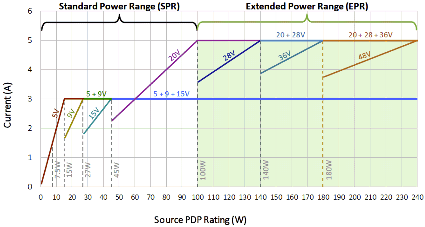
USB Type-C charging is becoming popular amongst consumers because it’s convenient to use the same USB Type-C cord for many household items. USB Type-C is even expanding to support higher-power applications such as power tools and e-bikes. As shown in Figure 1, while USB Type-C used to support up to 100 W of power with Standard Power Range (SPR), it can now support as much as 240 W with Extended Power Range (EPR).
 Figure 1 USB Power Delivery (PD)
ranges.
Figure 1 USB Power Delivery (PD)
ranges.Behind the goal to be able to get charge from different types of USB Type-C source including SPR and EPR comes the challenge of designing an application that can support the entire voltage range of USB Type-C PD EPR. Imagine a leaf blower designed with five-cell lithium-ion (Li-ion) batteries and a USB Type-C input. Because the batteries are Li-ion, the full charge voltage of each battery cell is 4.2 V, which means that the voltage of the battery pack (VBATT) at full charge is 21 V. The owner of the leaf blower could use many USB wall adapters, but for this example, assume that they have a 45- or 140-W USB Type-C wall adapter, which means that the input voltage (VIN) to the battery charger could be 15 V or 28 V. The question now is how to fulfill these requirements:
- Charge the battery when VIN > VBATT or VIN < VBATT.
- Charge the battery as quickly as possible to minimize charging time.
- Keep the leaf blower cool during charging to help prevent overheating.
- Use one charger IC across different platforms with different cell counts.
The component that addresses each of these requirements is a buck-boost battery charge controller with external switching field-effect transistors (FETs). The buck-boost portion of the charger helps address the first requirement to have VIN > VBATT or VIN < VBATT. Using four FETs and an inductor in the configuration shown in Figure 2, the battery charger can operate in buck mode when VIN > VBATT shown in Figure 3 and in boost mode when VIN < VBATT shown in Figure 4.
The external FETs help address the second requirement. Selecting external FETs improves thermal performance and helps reduce charge times with a higher charge-current capability. In addition, external FETs provide a larger area to dissipate heat during charging. For these reasons, an external metal-oxide-semiconductor FET buck-boost battery charger enables applications that can handle the new USB PD EPR levels and help provide a quick charging experience.
 Figure 2 H-bridge configurations of a
buck-boost charge controller.
 Figure 3 Buck mode configuration when
VIN > VBATT. Q1 and Q2 switch on and off, Q3 is off and Q4 is on.
  Figure 4 Boost mode configuration when
VIN < VBATT. Q3 and Q4 switch on and off, Q2 is off and Q1 is on.