SNAU291 October   2023


  1.   1
  2.   Description
  3.   Features
  4.   Applications
  5.   5
  6. 1Evaluation Module Overview
    1. 1.1 Introduction
    2. 1.2 Kit Contents
    3. 1.3 Specification
    4. 1.4 Device Information
  7. 2Hardware
    1. 2.1 EVM Quick Start
      1. 2.1.1 Hardware Setup
      2. 2.1.2 EVM Measurements
    2. 2.2 Device Operation Modes
    3. 2.3 EVM Configuration
      1. 2.3.1 Power Supply
      2. 2.3.2 Logic Input and Outputs
      3. 2.3.3 Clock Input
      4. 2.3.4 Clock Outputs
      5. 2.3.5 Status Outputs, LEDs and Test Points
  8. 3Software
    1. 3.1 Software Installation
      1. 3.1.1 Software Setup
      2. 3.1.2 Program and Setup
    2. 3.2 TICS Pro LMKDB1108 Software
      1. 3.2.1 Input
        1. 3.2.1.1 Input Interface Type
        2. 3.2.1.2 Input Termination
        3. 3.2.1.3 Auto Output Disable (AOD)
        4. 3.2.1.4 LOS Event
        5. 3.2.1.5 LOS Readback
      2. 3.2.2 Device Info
        1. 3.2.2.1 EVM Setup
        2. 3.2.2.2 SMBus
      3. 3.2.3 Output
        1. 3.2.3.1 SMBus
        2. 3.2.3.2 OE Pin Control
        3. 3.2.3.3 Side Band Interface (SBI)
  9. 4Implementation Results
    1. 4.1 Typical Phase Noise Characteristic
  10. 5Hardware Design Files
    1. 5.1 Schematics
    2. 5.2 PCB Layouts
    3. 5.3 Bill of Materials (BOM)
  11. 6Compliance Information
    1. 6.1 Compliance and Certifications
  12. 7References

Clock Input

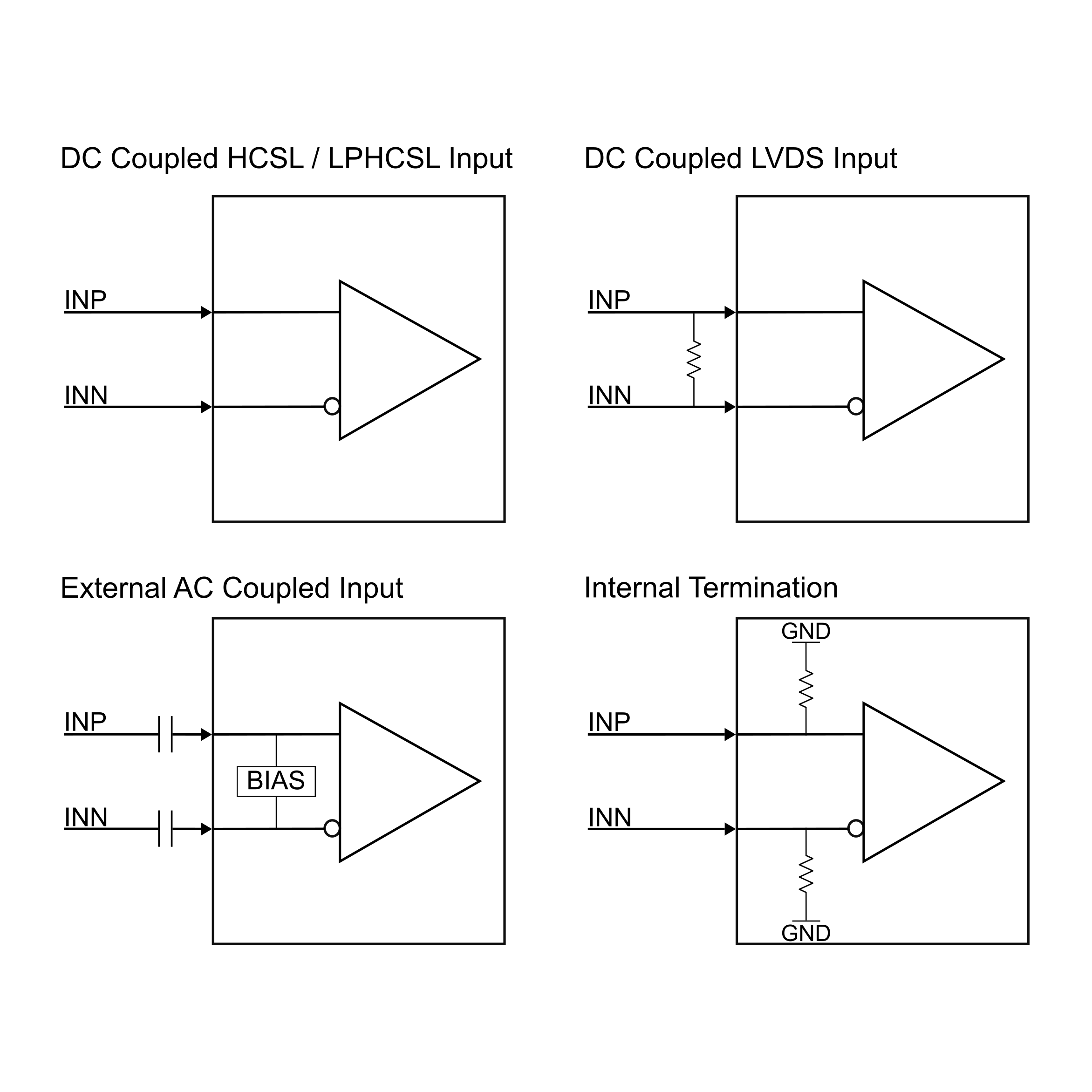
LMKDB1108 can support different input interfaces depending on the input swing and common mode voltage. There are four input interfaces type that can be configured on LMKDB1108 using external components and internal termination schemes as shown in Figure 3-1. If using signal generator, then make sure to populate R34 with a 100-Ω resistor or use internal / external 50-Ω termination to ground.

  1. DC Coupled HCSL / LP HCSL Input.
  2. DC Coupled LVDS Input.
  3. External AC Coupled Input.
  4. Internal 50-Ω to ground terminations.

    GUID-20231009-SS0I-CFRZ-2LMB-K4ZGGXCBM5MN-low.png

    Figure 2-1 Input Interfaces

    Table 3-9 outlines how to setup all different interfaces supported by LMKDB1108.

    Table 2-9 Input Interfaces
    Input Interface Configuration
    DC coupled HCSL / LPHCSL This is default EVM and device configuration. R101 and R103 values are 0-Ω and Input Interface Type on Input page is selected to DC Coupled.
    DC coupled LVDS input Populate R102 with a 100-Ω resistor and set Input Interface Type on Input page to DC Coupled.
    External AC coupled input Replace R101 and R103 with 0.1 uF capacitor and set Input Interface Type on Input page to AC Coupled.
    Internal termination To enable internal 50-Ω to ground terminations. Set the Input Termination on Input page to Enabled.