SNOT030B March 2022 – July 2026 TLV3601 , TLV3603 , TLV3604 , TLV3605 , TLV3801 , TLV3811 , TLV3901
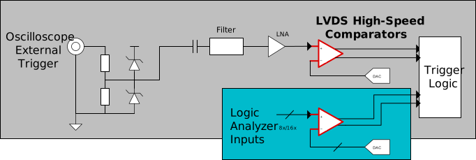 Figure 1 Concept Diagram for Test and Measurement Systems
See more about this use case in this video: High-Speed Comparators in Test and Measurement.
Design Challenges
- Input signals can be bipolar in nature (contains both positive and negative voltages) and often requires level shifting by the LNA.
- For high-speed waveform capturing, oscilloscopes need to be able to trigger on very narrow pulse widths while maintaining timing accuracy.
- A logic analyzer's speed rating depends on how fast a signal can be detected at the equipment's inputs.
- When high-speed signals need to span large trace lengths or cables, signal restoration is required to maintain signal integrity.
How High-Speed Comparators Benefit the Systems
- A comparator's ability to operate from split supplies eliminates the need to level shift input signals, greatly simplifying the input signal path.
- High-speed comparator's narrow pulse width detection capability with minimum overdrive dispersion enables the capture of events that occur for short periods of time of varying amplitudes with high accuracy.
- Comparators with high-speed front ends and LVDS output stages are well-equipped to capture fast-toggling clocks and data lines.
- Input hysteresis and variable input thresholds allow high-speed comparators to restore signal integrity in the presence of noise and decreased signal strength.
| Part Number | Output Type | Min Pulse Width | Overdrive Dispersion | Toggle Frequency | Supply Range |
|---|---|---|---|---|---|
| TLV3801 and TLV3811 | LVDS | 240ps | 5ps | 3GHz | 2.7 to 5.25V |
| TLV3604 and TLV3605 | LVDS | 600ps | 350ps | 1.5GHz | 2.4 to 5.5V |
| TLV3601 and TLV3603 | Push-pull | 1.25ns | 600ps | 325MHz | 2.4 to 5.5V |
| TLV3901 | CML | 60ps | 5ps | 10GHz | 3.1 to 5.25V |