SNVU737A December   2020  – December 2021 LM5123-Q1


  1.   Trademarks
  2. 1Introduction
    1. 1.1 Applications
    2. 1.2 Features
  3. 2EVM Setup
    1. 2.1 EVM Characteristics
    2. 2.2 EVM Connectors and Test Points
    3. 2.3 EVM Configurations
      1. 2.3.1 Output Voltage Tracking
  4. 3Test Setup and Procedures
    1. 3.1 Equipment
  5. 4Test Results
    1. 4.1 Efficiency
    2. 4.2 Load Regulation
    3. 4.3 Thermal Performance
    4. 4.4 Start-up Waveforms
    5. 4.5 Steady State Operation
    6. 4.6 Load Transient Response
    7. 4.7 Output Voltage Tracking
  6. 5PCB Layers
  7. 6Schematic
  8. 7Bill of Materials
  9. 8Revision History

EVM Setup

Section 2 describes the operating conditions for the EVM, as well as the configuration points of the evaluation module.

Figure 2-1 EVM Photo
GUID-666523DD-E40C-42E0-B2AB-9A7D69FD5E3B-low.png
CAUTION: Prolonged operation with low input at full power will cause heating of Q3 and Q2.
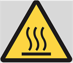
Board surface is hot. Do not touch! Contact may cause burns.