SNVU769A September 2021 – October 2022
5 Watchdog
This section provides the basic overview of the SPI based Q&A watchdog algorithm implemented on the EVM. Please refer LP87745-Q1 device data sheet for more detailed information about device watchdog functionality. This watchdog requires specific SPI messages from the host MCU in specific time intervals to detect correct operation of the MCU. On the EVM, MSP432 MCU is used as a host MCU.
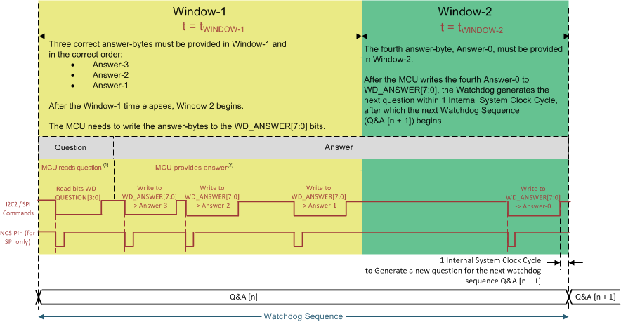
During operation, the device provides a 4-bit question for the MCU and the MCU calculates the required 32-bit answer. This answer is split into four answer bytes: Answer-3, Answer-2, Answer-1 and Answer-0. The MCU writes these answer bytes one byte at a time into WD_ANSWER[7:0] from the SPI interface.
A good event occurs when the MCU sends the correct answer-bytes calculated for the current question in the correct watchdog window and in the correct sequence. This sequence is visualized in Figure 5-1
A bad event occurs when one of the events that follows occur:
- The MCU sends the correct answer-bytes, but not in the correct watchdog window.
- The MCU sends incorrect answer-bytes.
- The MCU returns correct answer-bytes, but in the incorrect sequence.
 Figure 5-1 Watchdog
Sequence in Q&A Mode
Figure 5-1 Watchdog
Sequence in Q&A ModeIn GUI, there are two sections in configuration tab for watchdog configurability. Figure 5-2 illustrates the watchdog validation section in GUI, where the delays between the WD Answers can be configured and watchdog status for different interrupts and errors can be observed. And if required status can be cleared through clear buttons available next to the each status. In the other watchdog configuration section, watchdog can be enabled or disabled along with other watchdog configurable parameters as shown in Figure 5-3. For further information on watchdog configuration, refer to the data sheet of LP8774x-Q1 https://www.ti.com/lit/pdf/SNVSBE7 for watchdog section.