SPRUFR5I June 2008 – October 2019
2 Hardware Setup
This guide sets up the board to use onboard USB emulation and uses the 5-V supply of the USB to power the board.
Follow these steps to set up the hardware:
- Unpack the DIMM style controlCARD.
- Spread open the winged retaining clips on connector J1.
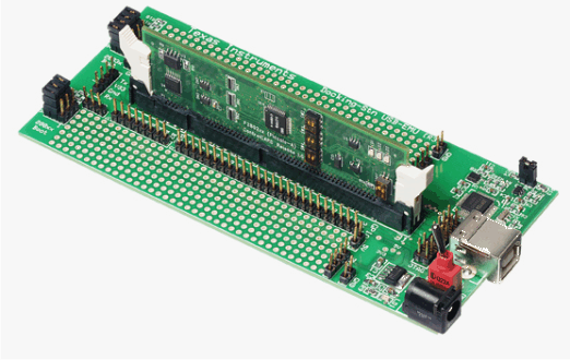
- Sit the DIMM card loosely in the connector slot. Ensure to align the two keyed notches and position the card bottom corners inside the retaining clips (see Figure 2).
- Push down vertically using even pressure from both ends of the card until the clips snap and lock.
- Place switch 1 (SW1) in the ON position, then connect the USB cable to USB connector JP2.
- Once you download the TI Software or are ready to run your own project, turn on the board power by putting SW1 in the USB position. This allows the board to use the 5 V of the USB as the supply voltage.
- For full details (schematics, pin-out table, and so on) of the hardware see the Hardware Developer’s package, DockingStnHWdevPkg.
NOTE
To remove or eject the card, simply spread open the retaining clips with your thumbs.
 Figure 2. Retaining Clips