SPRUIC4D January 2017 – June 2022
4.1 XDS100v2 Emulator and SCI/UART Connectivity
The F280049C controlCARD provides on-board emulation and USB-to-UART adapter functionality. This allows for a convenient method to debug and demo the F280049C MCU.
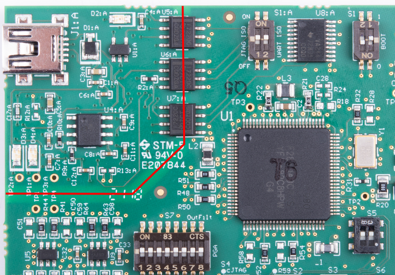
The FTDI chip, its support circuitry, and associated isolation components are placed in Macro A, the left section of the controlCARD. Each of these components contains an additional A within the component reference designator (that is R2:A for resistor 2 in Macro A).
Each F280049C controlCARD’s XDS100v2 is programmed with a fixed serial number. If a debug session must involve two or more F280049C controlCARDs, each controlCARDs must have a unique serial number, and some must be reprogrammed, see: https://software-dl.ti.com/ccs/esd/documents/xdsdebugprobes/emu_xds100.html (under Additional Information).
The configuration of the switches on S1:A (shown in Figure 4-1) determine whether the onboard emulator is active, whether an external emulator can be used, or whether the device will boot from FLASH/peripherals.
 Figure 4-1 XDS100v2 Emulation Circuitry and Isolation Circuitry is Denoted by :A