SPRUIJ3B November 2018 – April 2021
2.2 Connection Details
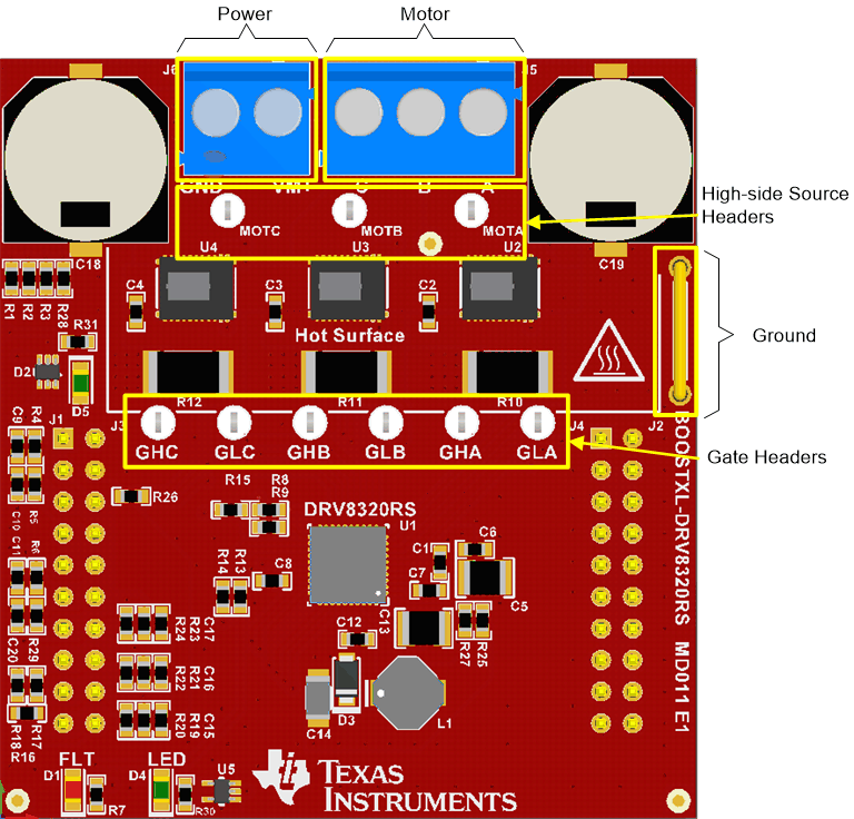
Figure 2-2 shows the power connector and motor phase connector. A supply voltage ranging from 6 to 54 V from a battery or a DC voltage source is connected to the voltage supply pins. Three phases of the BLDC motor are connected to the three-phase motor socket provided on the BOOSTXL-DRV8320RS.
 Figure 2-2 Connections
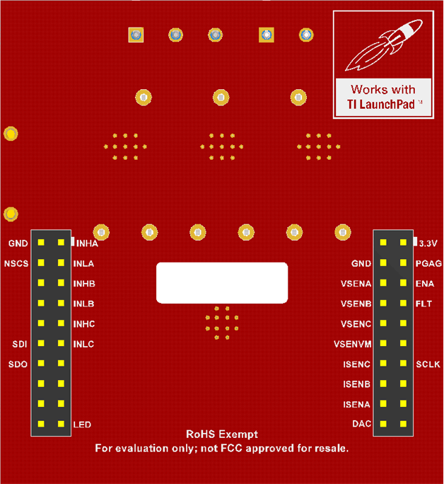
Figure 2-3 shows the connections required for the proper functioning of the software. A detailed description of each pin's function can be found in Table 2-1.
 Figure 2-3 Jumper Connections 1
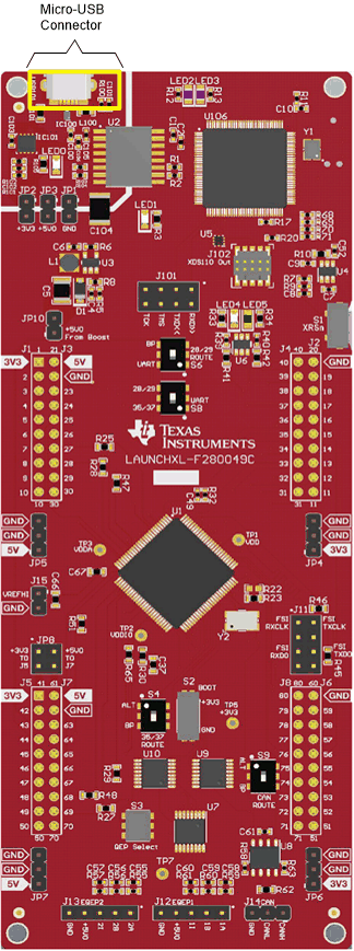
Figure 2-4 shows the LAUNCHXL-F2800049C. Only one cable is required to provide communication and power to the LaunchPad's onboard XDS110 emulator. Because the DRV8320RS provides power to the F280049C it is important to configure the jumpers as described in Table 3-1 to avoid shunting separate sources together.
 Figure 2-4 Micro-USB Connection