SSZT155 june 2021 INA228-Q1 , INA229-Q1 , INA240-Q1
The proliferation of 48-V battery systems in vehicles has created a need for high-precision, multidecade current measurement to maximize the efficiency of the battery management system (BMS). In this article, I will discuss the challenge when measuring up to five decades of current and analyze methods to solve this challenge. I will also discuss how additional diagnostic functionalities can aid in your functional safety calculations.
Current Measurement in a 48-V BMS
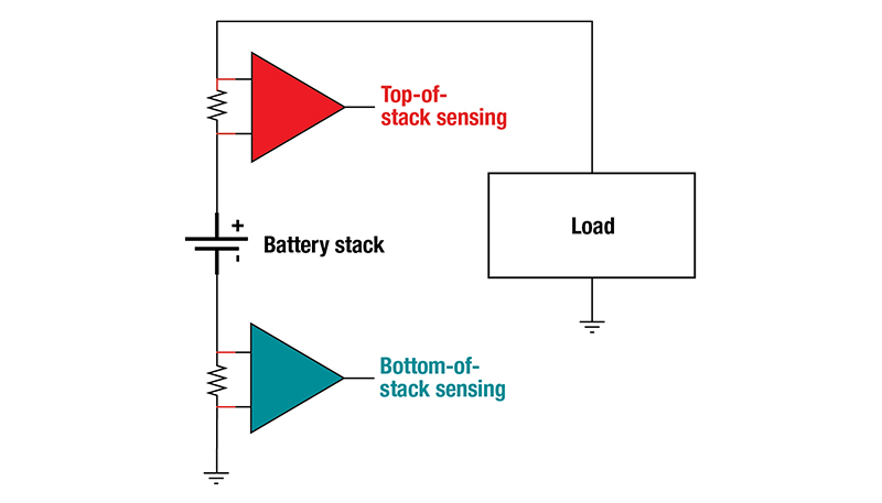
Let’s start by analyzing where current measurement occurs in a BMS by looking at Figure 1.
 Figure 1 Simplified Automotive BMS Current-measurement Locations Identified as Top of Stack or Bottom of Stack
As shown in Figure 1, the two most common locations are either top of stack or bottom of stack.
Our TI Precision Labs – Current Sense Amplifiers video series discusses the pros and cons of using each location in detail. For most 48-V BMS, implementing the top-of-stack location detects more potential fault conditions.
Many BMS will implement two measurements to meet their functional safety goals. One of them must be high precision in order to monitor the state of charge of the battery. The second measurement does not need such precision – it is simply for comparison to ensure that the primary measurement is in the correct range. The secondary measurement is often at the opposite location (bottom of stack) of the primary measurement, and thus uses a completely different shunt resistor. Alternatively, using a different technology such as a magnetic current sensor may provide a functional safety redundant path.
The Need for a Multidecade Measurement Range in 48-v BMS
Next, I want to discuss why an automotive BMS application may need to measure across multiple decades of current. Two operational modes determine the high end of this range: battery charging and traction motor operation.
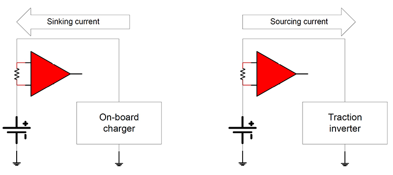
Either of these two use cases could potentially see currents as high as 1,000 A. Rapid charging of the 48-V battery will require this level of high current to minimize the charging time, while the traction motors under maximum torque may need to support 1,000-A peak current capability. These two use cases also highlight the need for bidirectional current measurement, as shown in Figure 2.
 Figure 2 Automotive BMS Current Measurement Has Both Sourcing and Sinking Current Requirements
While charging, the battery will be sinking current from the onboard charging system and sourcing current to the traction inverter while the vehicle is in motion.
At the other end of the current-use spectrum would be the 100-mA range for vehicle-off operation, such as remote start monitoring, keyless entry or system firmware updates.
The Five-decade Challenge
Now that you understand why five decades are necessary, your first step is to determine the shunt resistor value that you will need in order to measure the maximum current level. In addition to the maximum current level, you will need the full-scale input of the measurement device for this calculation. For a bidirectional analog-out device, the supply voltage, the swing to supply and the reference voltage (which is a voltage applied that sets the output level when the input is zero) will determine the maximum output swing; dividing the maximum output swing by the gain determines the full-scale input range. For a digital device, the data sheet normally defines the full-scale input. Then you simply use Figure 1 and Figure 1 to divide the full-scale input value by the maximum current to determine the maximum shunt resistor value.
Analog Output:
 Figure 3 (1)
Digital Output:
 Figure 4 (2)
The actual shunt resistor value should be less than the value calculated to ensure that you stay out of any saturation caused by system tolerances.
Once you have chosen your shunt resistor value, the next item to consider is what level of error you can accept in your implementation. Figure 1 is a root-sum-square (RSS) equation for calculating the error, since it is statistically improbable that all errors will be at their worst simultaneously:
 Figure 5 (3)
The video series that I mentioned earlier also has details on these calculations.
For my calculations, I compared the TI INA240-Q1 (specifically the INA240A1-Q1 option with 20 V/V gain), an ultra-precise high-voltage (80-V) analog current-sense amplifier, to the INA229-Q1, a 20-bit, 85-V digital power monitor. Table 1 summarizes both the maximum shunt value and expected error calculations starting from the device specifications.
| Device option | INA240A1-Q1 | INA229-Q1 | ||
|---|---|---|---|---|
| Common-mode voltage | 48 V | |||
| VS | 5 V | |||
| Swing to supply | 200 mV | |||
| VREF | 2.5 V | |||
| Maximum unidirectional output voltage | 2.3 V | |||
| Nominal gain option | 20 V/V | Unity | ||
| Gain error at 25°C | 0.2% | 0.1% | ||
| Gain drift | 2.5 ppm/°C | 20 ppm/°C | ||
| Maximum gain error at 125°C | 0.23% | 0.3% | ||
| Maximum gain at 125°C | 20.05 V/V | |||
| Maximum unidirectional input voltage | 114.7 mV | 163.84 mV | ||
| Maximum 25°C input offset voltage | 25 µV | 1 µV | ||
| Input offset voltage drift | 250 nV/°C | 10 nV/°C | ||
| Maximum 125°C input offset voltage | 50 µV | 2 µV | ||
| Maximum unidirectional current | 1,000 A | |||
| Maximum shunt resistor value | 114.7 µΩ | 163.8 µΩ | ||
| Chosen shunt resistor value | 100 µΩ | 150 µΩ | ||
| RSS error calculated at: | 25°C | 125°C | 25°C | 125°C |
| 1,000 A | 0.21% | 0.24% | 0.10% | 0.30% |
| 100 A | 0.64% | 0.89% | 0.10% | 0.30% |
| 10 A | 6.1% | 8.6% | 0.27% | 0.43% |
| 1 A | 61% | 86% | 2.5% | 3.2% |
| 100 mA | 610% | 860% | 25% | 31% |
The Five-decade Challenge Solved!
As you can see, solving the five-decade challenge for a 48-V BMS requires:
- A large-enough full-scale input range to enable a large-enough shunt resistor at the maximum current and thus overcome the offset error.
- A low total input offset voltage, including the effects of common-mode rejection ratio and power-supply rejection, to enable the low ohmic shunts driven by the maximum current level.
The INA229-Q1’s 164-mV full-scale input range and maximum 2 µV of total offset voltage over temperature at a common mode voltage of 48 V enables five decades of measurement with a single device across a single shunt resistor. In addition, this device has as the ability to monitor a 48-V battery voltage combined with flexible alert options such as over- and undervoltage and over- and undercurrent.
Additional Resources
- Read the application note, “Getting Started with Digital Power Monitors.”
- Check out the application brief, “Shunt-Based Current-Sensing Solutions for BMS Applications in HEVs and EVs.”
- Download the INA229-Q1 data sheet.