SSZT175 april 2021 DAC53204 , DAC53701 , DAC63004 , DAC63204
The technical article, “What is a smart DAC?” explained what a smart digital-to-analog converter (DAC) is and how it can bring value to many applications. Smart DACs can improve design efficiencies by reducing the burden of software development, and they provide many useful functions that would otherwise require external components that may have lower performance or similar performance with an increased cost. The integrated features of smart DACs provide high precision at a lower system cost.
In this article, we will discuss how a smart DAC can produce pulse-width modulation (PWM) signals controlled directly from an analog signal through the feedback pin of the device. The DAC53701 used in this example features nonvolatile memory (NVM) that enables the storage of all register configurations after initial programming, even after a power cycle.
For long-distance control and fault management in automotive lighting and industrial applications, smart DACs can be used as PWM generators to provide configurable analog-to-PWM translation, duty-cycle translation and general-purpose input (GPI)-to-PWM conversion at a lower system cost and with higher performance than competing solutions. Let’s take a look at each of these in detail, starting with simple PWM generation.
PWM Function Generation
Unlike microcontrollers (MCUs) or timer-based solutions, smart DACs have a continuous waveform generation (CWG) mode that enables simple PWM generation. The function generator has the ability to output triangle waves, sawtooth waves with rising or falling slopes, and square waves. You can use the configuration registers to customize the slew rate and the high and low voltage levels of the waves. The function generator can create a 50% duty-cycle square wave with a limited number of adjustable frequencies.
Analog-to-PWM Translation
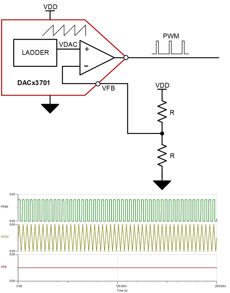
For applications such as temperature to PWM, smart DACs create an analog-to-PWM output by feeding a sawtooth or triangle wave into one of the inputs of the internal output buffer and the threshold voltage into the other input. The DAC53701 feedback pin exposes the feedback path between the output and inverting input of the internal output buffer, enabling the buffer’s use as a comparator. In the example shown in Figure 1, an analog input voltage (VFB) created by a resistor divider is applied to the feedback pin. Comparing a triangular waveform generated by the DAC53701 against VFB will produce a square wave. Using a negative temperature coefficient resistor in place of one of the resistors in the ladder produces a variable duty cycle.
 Figure 1 Analog-to-PWM Circuit and Simulation
(1) and (2) calculate the frequency setting of the input waveform to generate PWM. The registers in these equations are programmed to the smart DAC.
 Figure 2 (1) and (2)
Margin-high is the high-voltage level of the waveform, and margin-low is the low-voltage level. The duty cycle of the PWM output correlates with the margin-high, margin-low and VFB applied to the feedback pin, as expressed by (3):
 Figure 3 (3)
GPI-to-PWM Conversion
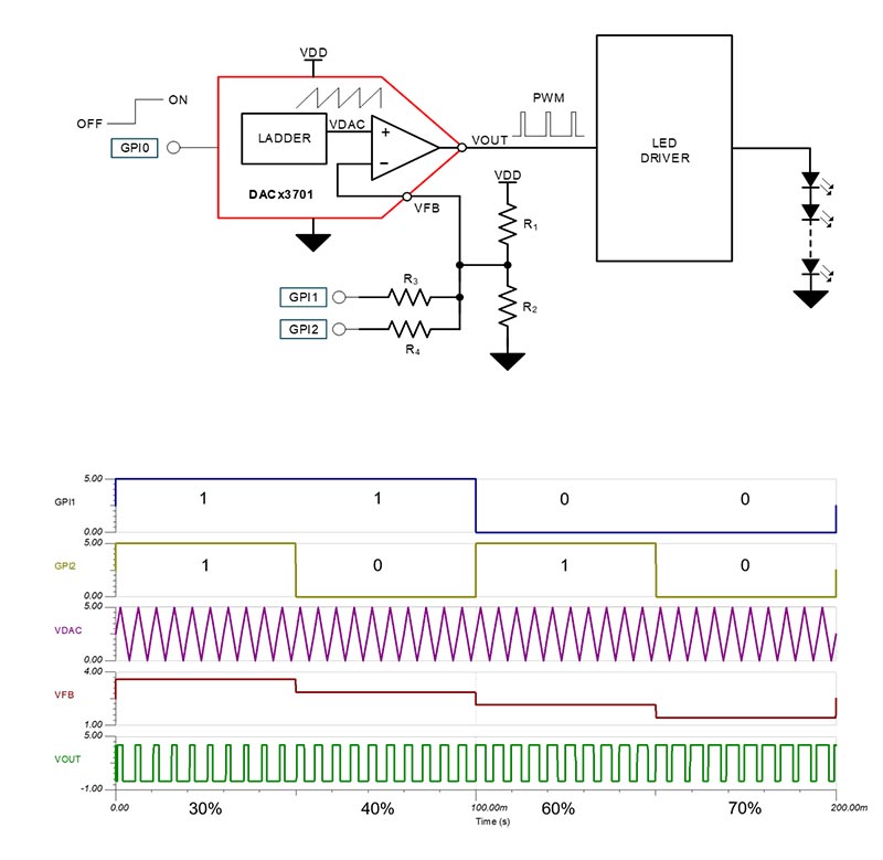
In GPI-based dimming for LED automotive taillights, smart DACs provide additional digital interfacing by expanding the feedback resistor divider network, as seen in Figure 4. Adding two resistors to the DAC53701 feedback network shown in Figure 1 creates two new GPI pins. The voltage at the feedback pin changes depending on the level of GPI1 and GPI2.
As discussed in the previous section, the voltage at the feedback pin, along with the margin-high and margin-low voltages of the triangular or sawtooth waveform coming from CWG, determine the duty cycle of the PWM output. GPI0 can provide on and off functionality to the system by powering up and powering down the DAC53701, or start and stop functionality for CWG.
 Figure 4 GPI-to-PWM Circuit and Simulation
555 Timer Replacement
A smart DAC’s PWM duty cycle is controlled through changes to the triangular- or sawtooth-wave margin-high and margin-low voltages, while the frequency is controlled by setting the slew rate for the DAC. These programmable settings remove the need for additional timing circuitry such as 555 timers. Replacing 555 timers with smart DACs has multiple advantages. A typical 555 timer is 9 mm by 6 mm and requires external components to set its operating frequency. Smart DACs come in a 2-mm-by-2-mm quad flat no-lead package and require fewer external components, and their frequency is not controlled by any external components that are subject to drift.
PWM Duty-cycle Conversion
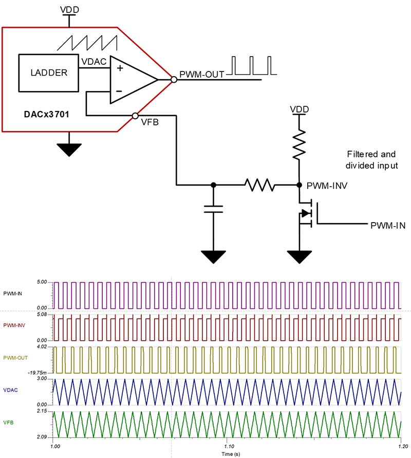
When you need to adjust the PWM duty cycle to fit the input ranges of various devices in your system, smart DACs can translate the duty cycle of an input PWM signal. Adding a resistor-capacitor (RC) filter to the PWM input signal will translate it to an analog voltage, applicable to the smart DAC’s feedback pin. In most cases, you will need to invert the PWM input signal because the RC filter will provide a larger analog voltage for larger duty cycles. A larger analog voltage on the feedback pin will give a smaller duty cycle output wave from the DAC53701.
After inverting the input PWM and adding the RC filter, it is possible to vary the duty cycle of the output by dividing down the output of the RC filter using a resistor divider, or adjusting the margin-high and margin-low values of the triangular or sawtooth wave from the DAC53701 CWG according to the Figure 5. The schematic and simulation using the in Figure 5 shows the inversion and filtering of the input PWM waveform, as well as the duty-cycle translation using the DAC53701.
 Figure 5 PWM Duty-cycle Conversion Circuit and Simulation
Conclusion
Smart DACs are a good fit for most designs or subsystems that need PWM generation, providing access to internal components as well as storage and programmability. Smart DACs can help take multiple inputs, converting temperature, resistance or GPI inputs to an accurate and controllable PWM signal.
Additional Resources
- Learn more about smart DACs in the technical article, "What is a smart DAC?"
- Browse the smart DAC FAQ on our TI E2ETM forums.
- View the DAC53701 data sheet.
- Explore three other devices in the smart DAC family, the DAC53204, DAC63204 and DAC63004.
- Explore TI's portfolio of smart DACs.