SSZT315 april 2020 BQ769142 , BQ76942 , BQ76952 , BQ76972
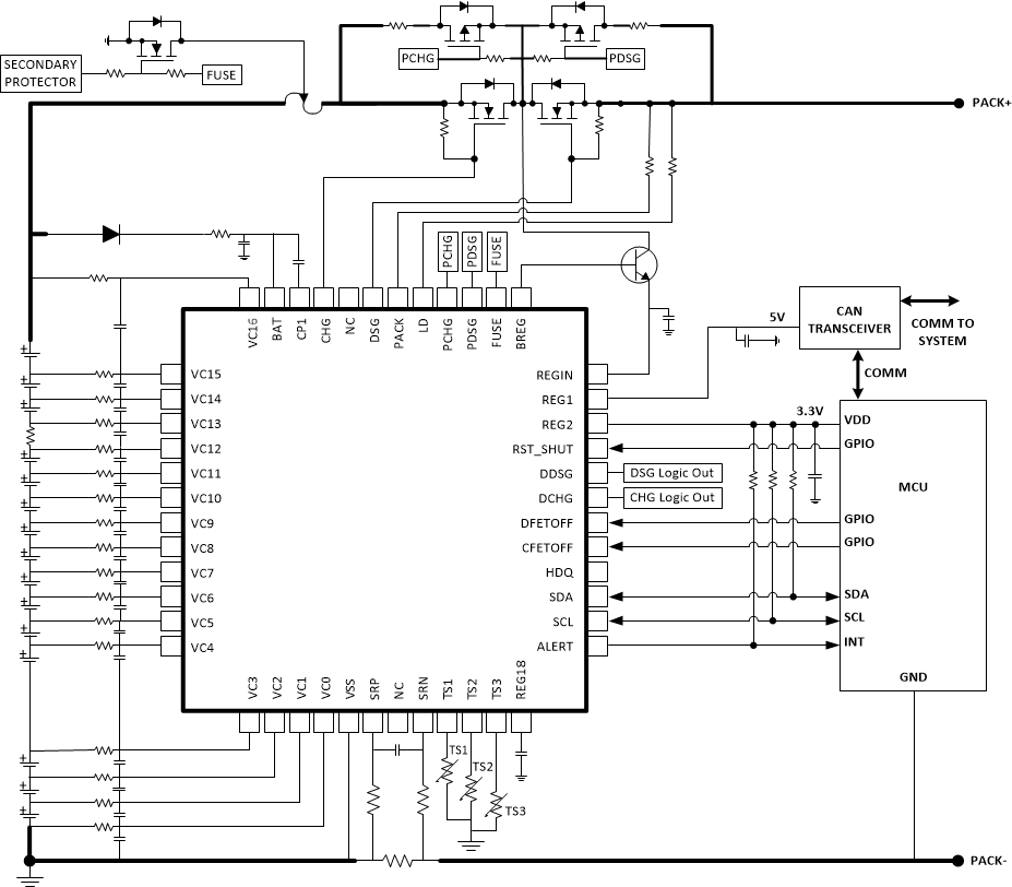
As reviewed in my earlier article, accurate monitoring of battery voltage, current and temperature is necessary to ensure the safe operation of battery-powered systems such as vacuum cleaners, power tools and e-bikes. In this article, I will focus on voltage monitoring of lithium-based batteries.
A key requirement of safety standards for lithium-based battery systems is that the cells should only operate within the specified voltage range provided by the cell manufacturer. This is critical, since overcharging a lithium-ion battery pack beyond this limit can result in fire or explosion. Overcharging is a very real danger in practice – all it takes is for a pack to be connected to a charger that was designed for a different system, which may try to charge to a voltage beyond what that particular pack allows. In order to ensure the safety of the entire system, the battery-management system must monitor the voltage of each cell in the pack and disable charging whenever any cell voltage reaches the maximum allowed by the cell manufacturer.
Similarly, it is also necessary to disable the battery pack if any cell voltage falls below the minimum manufacturer-specified voltage. When a cell remains at an excessively low voltage for an extended period of time, dendrites may form and make it dangerous to operate the cell further. Ultimately, it is critical to measure the voltage of each cell accurately in order to determine when to disable the pack and maintain safe system operation.
The newest additions to TI’s family of battery monitors and protectors, the BQ76942 (three cells in series [3S], up to 10S) and BQ76952 (3S up to 16S), integrate a 16-/24-bit delta-sigma analog-to-digital converter (ADC), which is multiplexed to measure each individual differential cell voltage, as well as other selected voltages in the system. Most voltages are reported using 16-bit values, although the 24-bit raw ADC data is also available in case you need better resolution for post-processing.
Synchronized voltage and current measurements
The BQ76942 and BQ76952 support synchronized measurements to measure current and cell voltage simultaneously. This is useful when analyzing the cell impedance, which can be used for predicting pack operation under high discharge loads. The 24-bit raw ADC readings for each cell voltage and synchronized current are stored as a pair. Cell voltage measurements are reported in units of millivolts, while voltages measured for the stack, PACK pin and LD pin are reported in units of centivolts (10 mV) or millivolts, as set in Settings > Configuration > DA Configuration in device data memory. Raw ADC readings are provided in units of counts.
Voltage measurements
Because of the differential and common-mode voltage range of the different signals digitized by the voltage measurement subsystem, each input to the ADC is specially designed for its specific use in the system. The differential cell voltage measurements are the most critical, and will typically vary between a voltage of ~2 V and ~4.5 V, with the lower terminal varying from 0 V (for the lowest cell in the stack) to as high as 67.5 V (for the 16th cell in the stack). The BQ76942 and BQ76952 support a differential cell voltage measurement range from -0.2 V to +5.5 V for each cell. The BQ76942 supports a maximum voltage on the cell input pins ranging up to +55 V, while the BQ76952 supports up to +80 V.
The voltages of the top of stack (the topmost cell input pin), PACK pin and LD pin are also digitized relative to VSS. A resistive divider (enabled only while a measurement is in progress) measures these voltages. The supported voltage range for these pins is also up to +55 V for the BQ76942 and up to +80 V for the BQ76952.
The BQ76942 and BQ76952 include two references. VREF1 is used by the voltage ADC. VREF2 is used by the Coulomb counter ADC, the internal REG18 low-dropout regulator and other blocks within the devices. As a diagnostic measurement to detect internal faults within the devices, the ADC regularly measures and reports the REG18 LDO voltage and the VSS pin voltage measurements.
The voltage ADC also measures an internal change in the base emitter voltage (ΔVBE), which is used to calculate the internal die temperature, and the voltage on several additional pins, which can be connected to external thermistors for measuring cell and field-effect transistor temperatures. I describe this temperature measurement subsystem in more detail in my article, “Improving temperature measurement accuracy in battery monitoring systems.”
The speed of data measurements varies depending on the power mode of the device, with measurement only taken in NORMAL or SLEEP modes.
Measurement loop – NORMAL mode
In NORMAL mode, as illustrated in Figure 1, the voltage measurements are performed using a continuous repeating loop, such that after the device completes each set of measurements, it immediately initiates a new set of measurements. The measurement loop contains a number of slots that are periodically measured as:
- The differential cell voltages serially.
- One of the top-of-stack, PACK or LD pin voltages on each loop (each parameter measured every three loops).
- One slot for internal temperature, REG18 voltage or VSS (one parameter measured every three loops).
Up to three slots for thermistors or general-purpose ADC pin measurements (each measured once every one to three loops).
 Figure 1 NORMAL Mode Measurement
Loop
Figure 1 NORMAL Mode Measurement
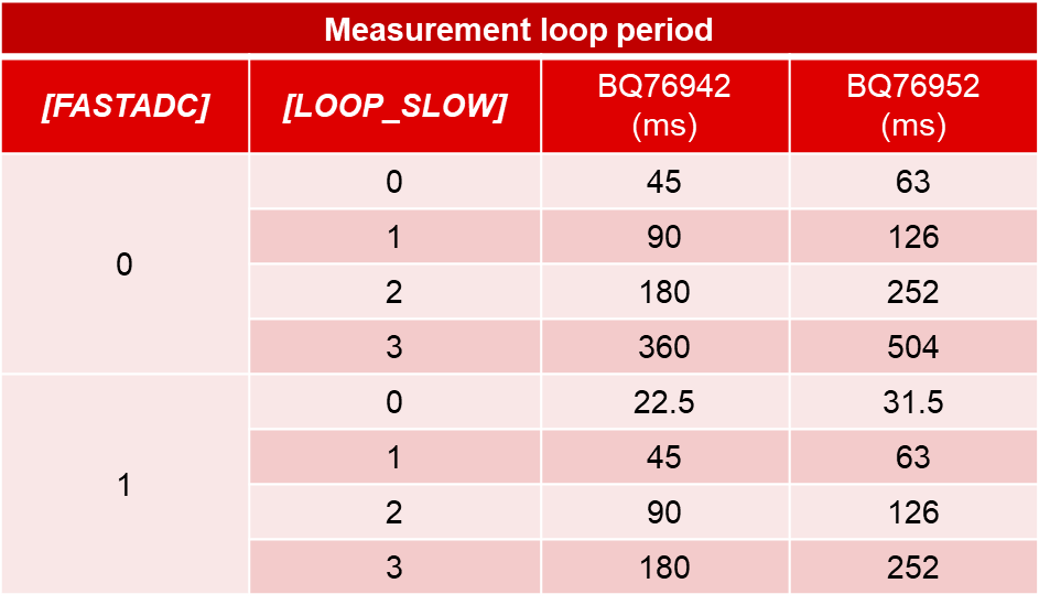
LoopThe sense resistor current (designated CC2) is measured simultaneously at every slot. The tmeas slot time default is 3 ms, but you can reduce that time to 1.5 ms by setting the [FASTADC] bit, with a reduction in conversion resolution. The measurement loop time (using 3-ms conversions and three or more thermistors) is 45 ms for the BQ76942 (10S), and 63 ms for the BQ76952 (16S).
It is possible to slow the measurement loop down by inserting unused voltage measurement slots to save power, using the [LOOP_SLOW] setting, as shown in Figure 2.
 Figure 2 Normal Mode Measurement Loop
Timing
Figure 2 Normal Mode Measurement Loop
TimingVoltage measurement loop – SLEEP mode
The BQ76942 and BQ76952 are configurable for automatic transition into SLEEP mode when the system current drops below a programmable threshold. This lowers power dissipation by reducing the frequency of voltage measurements. While the device is in SLEEP mode, voltage, temperature and current measurements are performed every Power: Sleep: Voltage Time interval (1 s to 255 s), as shown in Figure 3.
 Figure 3 SLEEP Mode Measurement
Loop
Figure 3 SLEEP Mode Measurement
LoopCell voltage measurements
The BQ76942 and BQ76952 measure each VCN-VCN-1, whether the connection is used for a cell or not. Customer settings in device data memory determine which pins connect to cells. Those pins not connected to cells are not used for pertinent protections. Inputs not used for cell connections can be shorted or used for interconnect measurement, as shown in Figure 4.
 Figure 4 Using Cell Voltage Inputs for
Interconnect Measurements
Figure 4 Using Cell Voltage Inputs for
Interconnect MeasurementsYou must account for the accuracy of the cell voltage measurement when determining whether to disable the battery pack. For example, if the pack must be disabled when a cell voltage exceeds 4.350 V, but the accuracy of the voltage measurement is only within ±25 mV, then the battery-management controller needs to disable the pack when the reported measurement exceeds 4.325 V, in case the error is -25 mV. However, the actual error may instead be +25 mV, meaning that the actual cell voltage is only 4.300 V. Thus, in this case, as much as 50 mV of usable battery capacity is unavailable due to the inaccuracy of the measurement. Clearly, the more accurate the voltage measurement of the cell voltages, the less cell capacity wasted.
The cell voltage measurements in the BQ76942 and BQ76952 are factory-trimmed to meet these specifications:
- ±5 mV at 2 V to ~5 V at 25°C.
- ±10 mV at 2 V to ~5 V, across 0°C to +60°C.
- ±15 mV at -0.2 V to ~5.5 V, across -40°C to +85°C.
In addition, the devices support optional calibration of cell offset and gain on the production line, in order to further optimize performance.
Conclusion
The voltage measurement subsystem in the BQ76942 and BQ76952 provides a critical function in the safety solution of a battery-powered system, giving the system the necessary information to determine when to disable a pack due to a cell voltage outside manufacturer specifications. The high performance of the voltage measurements, with their trimmed accuracy and high-speed data collection, enable you to optimize pack designs for safe system operation in a variety of applications, from vacuum cleaners to power tools to e-bikes.
Additional resources
- Read the application report, “Easy Configuration of BQ76942/52 Battery Monitors.”