SSZT367 november 2019 TPS92682-Q1
Electronic technology has advanced so that an electronic control unit (ECU) is required to control the functions of full LED automotive headlights. An ECU consists of mainly LED drivers for headlight functions such as high beams, low beams, daytime running lights, position lights, turn indicators and fog lights. In this article, I’ll explain the advantage of having a flexibly configurable LED driver.
When LEDs were first introduced into the automotive headlight space, high-side switches connected to LED drivers drove the corresponding LEDs in each of the headlight functions. Figure 1 shows a block diagram of a traditional automotive body control module (BCM) with LED drivers for corresponding headlight functions. The LED and input voltage relationship per headlight function determine the best DC/DC topology.
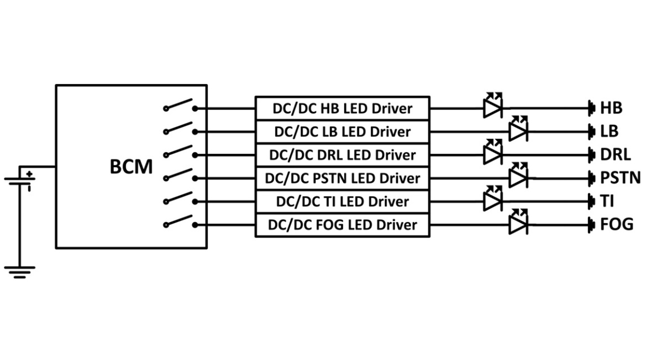 Figure 1 Traditional automotive BCM
with DC/DC LED drivers for LED headlights
Figure 1 Traditional automotive BCM
with DC/DC LED drivers for LED headlightsFigure 2 shows basic schematics of common DC/DC LED driver topologies and their voltage relationships.
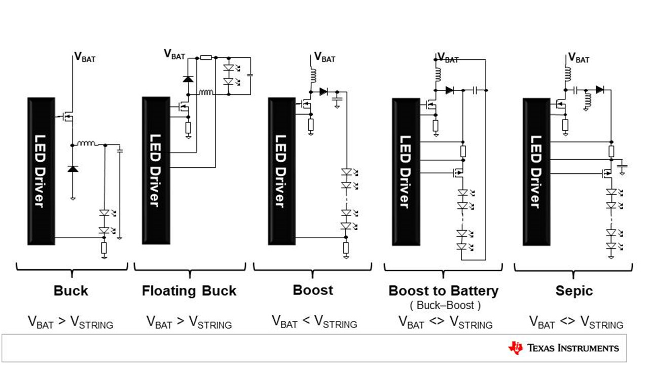 Figure 2 Basic schematics of common
DC/DC LED driver topologies
Figure 2 Basic schematics of common
DC/DC LED driver topologiesExcept buck LED drivers, which require a high-side metal-oxide semiconductor field-effect transistor (MOSFET), all other topologies can be implemented with a low-side MOSFET controller. Hence, a low-side MOSFET controller is one of the necessary elements to build a flexibly configurable LED driver.
As electronic technology advances and car manufacturers feel more comfortable adding electronic controls to their vehicles, a modern full LED automotive headlight will employ an ECU with a modernized BCM, including microcontrollers (MCUs). The ECU should be able to communicate through the MCU upon receiving commands from the BCM and all headlight functions are controlled accordingly. Figure 3 shows a modern architecture for a full LED automotive headlight.
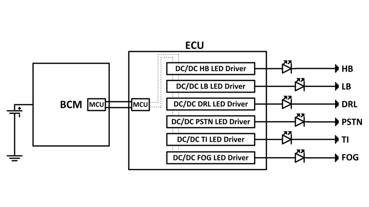 Figure 3 Modern architecture for full
LED automotive headlight
Figure 3 Modern architecture for full
LED automotive headlightThe MCU in the ECU receives information from the BCM to determine which headlight function to turn on or off. More advanced models might require the ECU to change individual headlight brightness based on BCM commands. It would be best to have an effective digital protocol control, such as SPI, within the ECU such that the MCU can communicate with individual DC/DC LED drivers through the digital interface.
The TPS92682-Q1 is a dual-channel low-side N-type MOSFET controller with Serial Peripheral Interface (SPI) for parametric setup through digital controls. With a low-side N-type MOSFET controller, different DC/DC LED driver topologies can be built, such as boost, boost-to-battery, single-ended primary inductor converter and floating buck. SPI enables the MCU to provide parametric setup information through digital protocols. More importantly, the dual-channel device has two fully independent controllers that can be programmed flexibly according to the ECU’s commands. As illustrated in Figure 4, it’s possible to build a six-channel ECU with three TPS92682-Q1 devices.
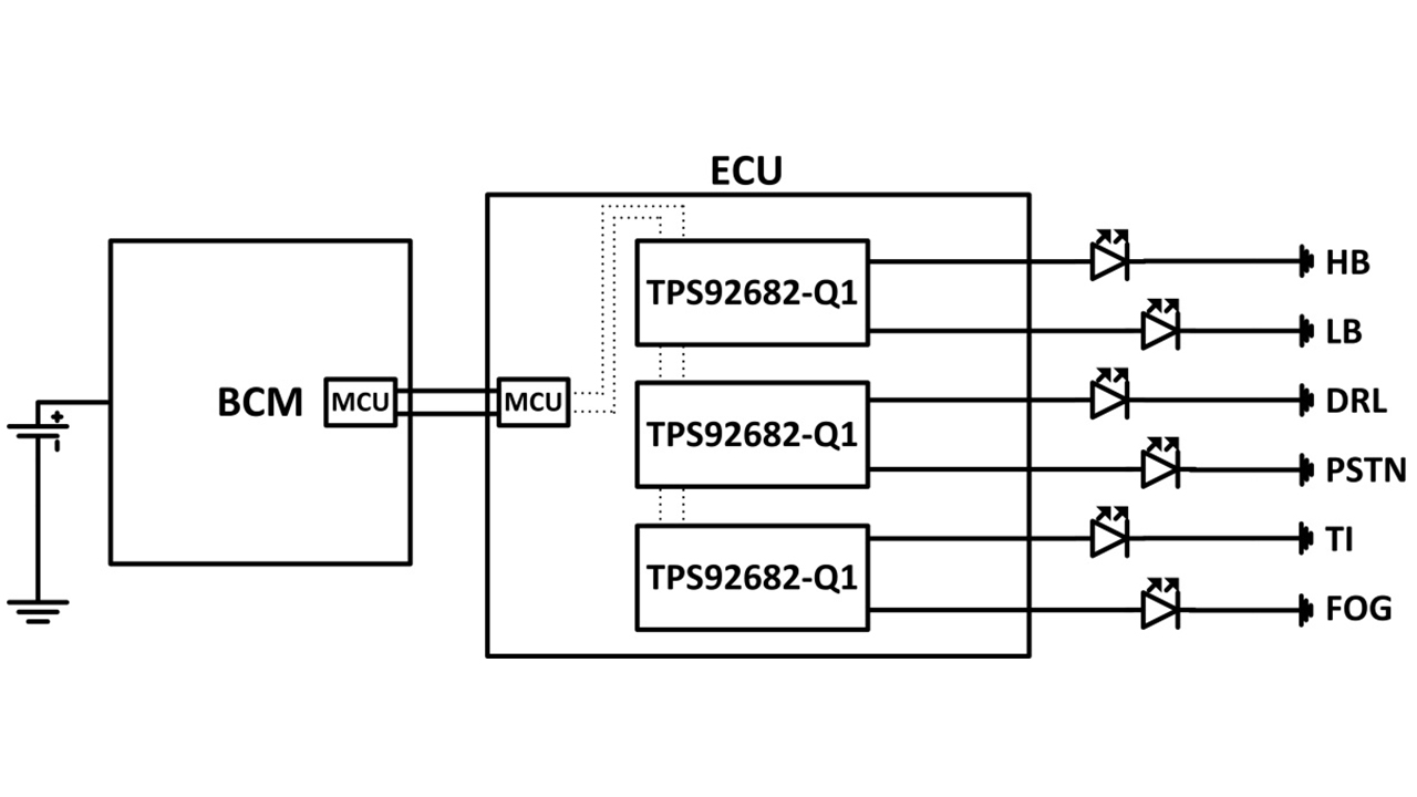 Figure 4 Six-channel ECU example block
diagram with the TPS92682-Q1
Figure 4 Six-channel ECU example block
diagram with the TPS92682-Q1The TPS92682-Q1 has the ability to configure channels to be current output or voltage output. Simple ECUs normally provide current sources to LEDs for different headlight functions. More advanced headlights, such as matrix LED headlights, require that the LED drivers be in a boost-to-buck configuration for pixel brightness control compatibility with LED matrix managers. Figure 5 shows a typical ECU block diagram for an advanced headlight.
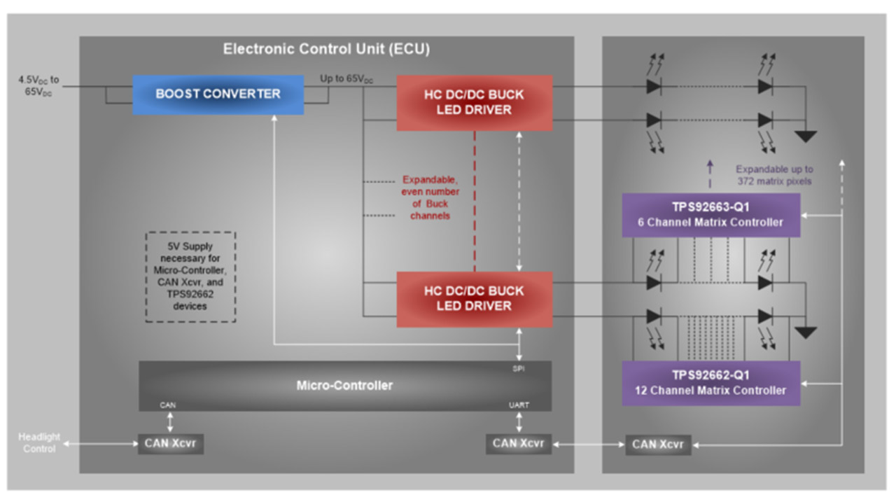 Figure 5 Typical ECU block diagram for
an advanced headlight
Figure 5 Typical ECU block diagram for
an advanced headlightThe two channels of the TPS92682-Q1 can be programmed to run as a two-phase voltage-output regulator. This enables high output power – up to 120 W. However, there are simple headlight LED drivers that require a boost-to-floating-buck architecture. By configuring one channel as a boost voltage output with another channel configured as a floating buck current output, it’s possible to configure a simple boost-to-floating-buck LED driver with a single TPS92682-Q1 device. Figure 6 shows a concept schematic of a boost-to-floating buck using the TPS92682-Q1.
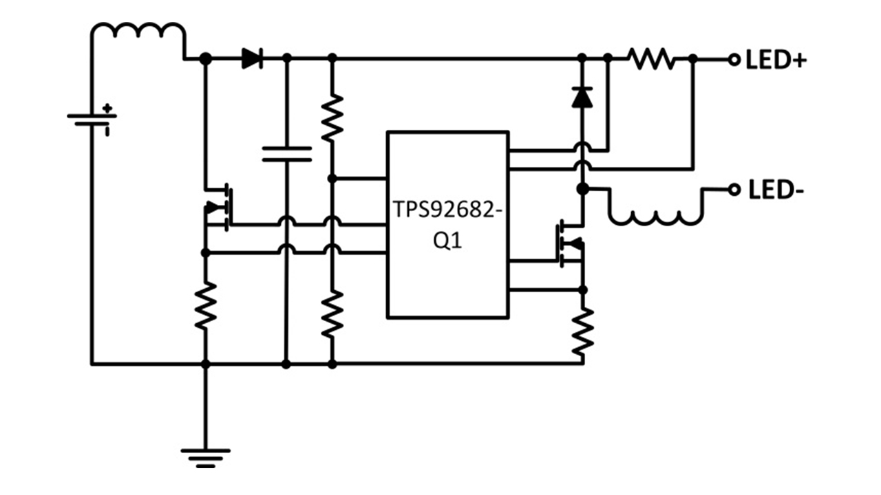 Figure 6 Concept schematic of a
boost-to-floating buck using the TPS92682-Q1
Figure 6 Concept schematic of a
boost-to-floating buck using the TPS92682-Q1As automotive headlights move from bulbs, xenon and high-intensity lamps to LEDs, the TPS92682-Q1 helps implement a flexibly configurable automotive headlight ECU that can communicate with a modern BCM.
Additional resource
- Learn how to select the right topology for LED matrix managers in “An ECU Architecture for Adaptive Headlights.”