SSZT393 october 2019 TPS92520-Q1
Advanced automotive headlights require dynamic lighting functionality to achieve road-safety-enhancing features like adaptive driving beam and adaptive front lighting systems. These features use LED matrix managers (LMMs) to perform dynamic brightness changes on individual LED pixels. The LED current of a headlight with normal brightness ranges from 350 mA to above 1 A. For such kind of current level, the board size built with traditional devices tend to be big. The trend of headlight is moving for more channels of dynamic lighting functions, there is a need to have a high-power-density DC/DC buck LED driver that supports dynamic load operations for further miniaturization of headlight driver systems.
Let’s review the electronic control unit (ECU) requirements for dynamic headlights implemented with LMMs. Because the LED stack or total string voltage changes dynamically with different road environments, it’s best if the current-providing LED drivers use the smallest possible capacitors. From [1], a boost-into-hysteretic buck architecture is the most optimal choice for ECUs. A buck converter provides a continuous output current to the LED in order to minimize the output capacitances, as shown in Figure 1.
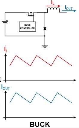 Figure 1 Output current of a buck LED
driver
Figure 1 Output current of a buck LED
driverA hysteretic control method best supports the dynamic brightness changes of LEDs, as shown in Figure 2.
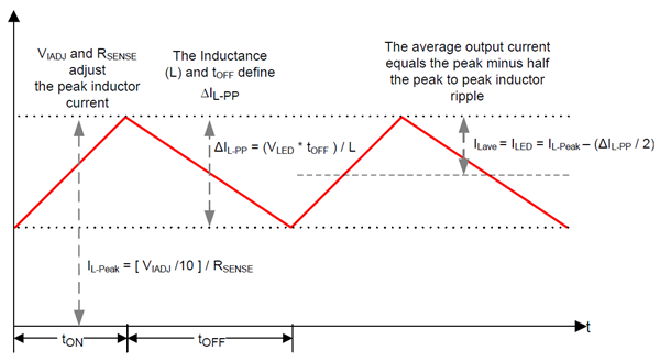 Figure 2 Hysteretic operation of a
DC/DC LED driver
Figure 2 Hysteretic operation of a
DC/DC LED driverThe nature of hysteretic operation is that the switching frequency will change according to the ratio of the output voltage and input voltage, as shown in Figure 3 and Figure 4, respectively.
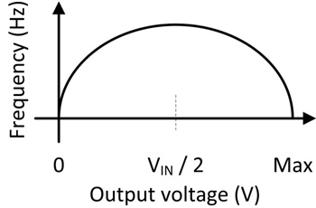 Figure 3 Switching frequency vs. output
voltage with a fixed input voltage (hysteretic operation)
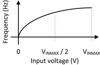 Figure 4 Switching frequency vs. input
voltage with a fixed output voltage (hysteretic operation)
Figure 4 Switching frequency vs. input
voltage with a fixed output voltage (hysteretic operation)Constant on-time control vs. hysteretic control – pseudo-fixed-frequency operation
For a hysteretic-controlled buck LED driver, the switching frequency changes according to the relationship between the input voltage and the output voltage. A changing switching frequency is sometimes not desirable, especially when trying to minimize electromagnetic interference (EMI). Most designs require a fixed switching frequency so that passive components can tackle the EMI generated around that switching frequency.
Figure 5 and Figure 6 are conceptual block diagrams of a constant on-time-controlled LED driver and the inductor current waveform.
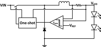 Figure 5 Conceptual block diagram of a constant on-time-controlled buck LED driver
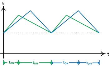 Figure 6 Inductor current ripple at different VIN-VOUT ratios
Since the on time is controlled according to the VIN and VOUT ratio, the duty cycle changes with a defined valley current limit. Therefore, the switching frequency is kept nearly constant, as shown in Figure 6.
Modern ECU requirements
A typical headlight ECU has an average of six to eight channels of output for different light uses: high beam, low beam, daytime running lights, position lights, turn indicators, fog lamps and so on. Figure 7 is a typical block diagram of an ECU. The total output power for such an ECU ranges from 60 W to 120 W. These specifications necessitate a small-sized yet efficient ECU solution – one that can fit in a tight spot within the car body without generating too much heat.
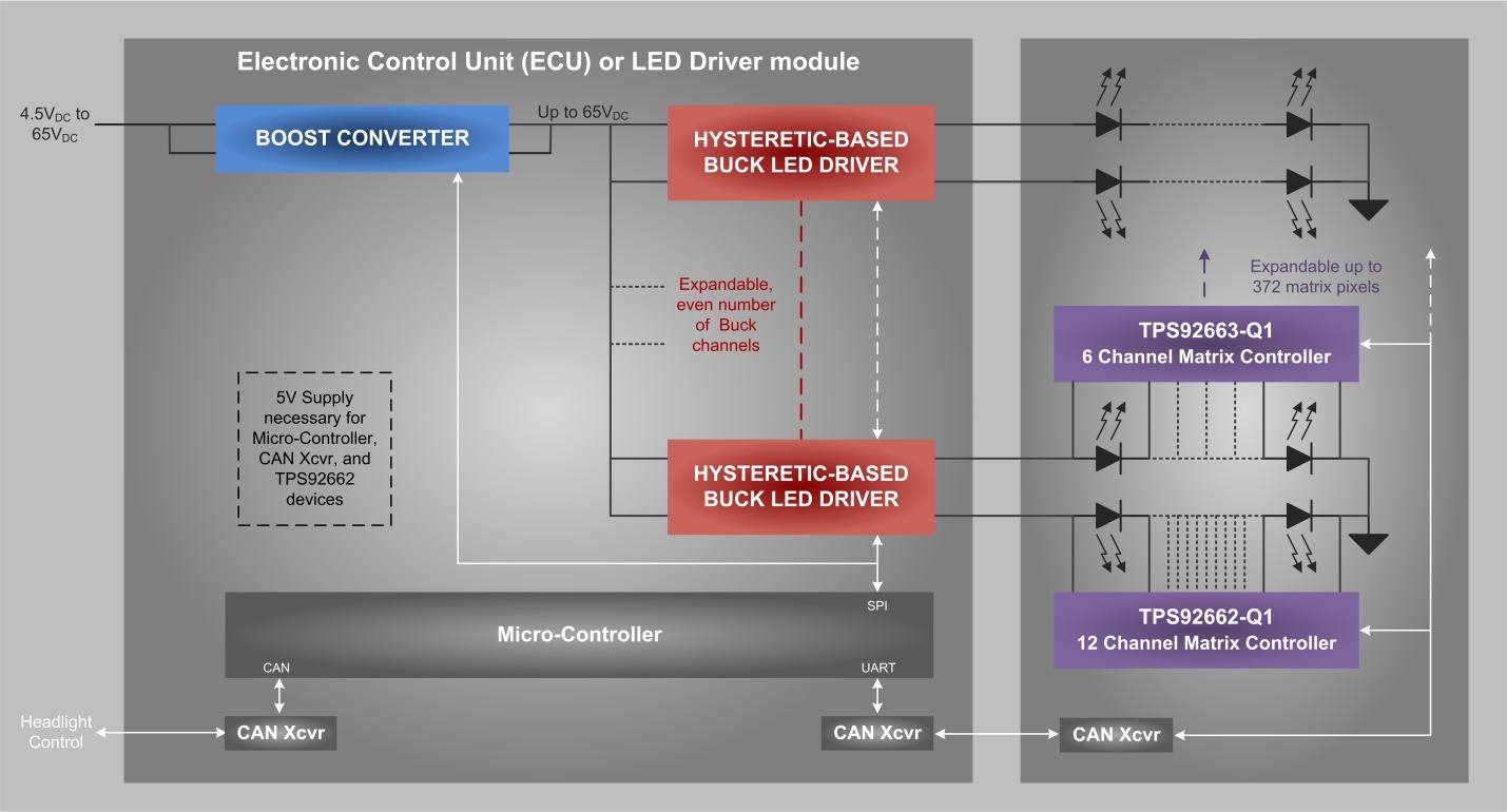 Figure 7 Typical ECU block
diagram
Figure 7 Typical ECU block
diagramThe power-density advantage of the TPS92520-Q1
The TPS92520-Q1 monolithic synchronous dual-channel constant on-time DC/DC buck LED driver helps reduce ECU solution size and provides high power-conversion efficiency. It has a programmable switching frequency with up to 2.2-MHz operation. It accepts Serial Peripheral Interface commands from a microcontroller, thus minimizing the number of passive components around the device for parametric setup.
In conclusion, a modern headlight ECU which supports dynamic lighting function requires buck LED drivers. With more and more channels having dynamic lighting functions, high-power-density LED drivers are required. High-power-density LED drivers (such as TPS92520-Q1) help implementing small-size, high performance headlight ECUs.