SSZT563 december 2018 TMP117
Other Parts Discussed in Post: TMP117
Wearable temperature patches are an emerging trend in patient temperature-monitoring systems. One of the biggest hurdles in designing these patches for use in a clinical setting is to meet the stringent accuracy requirements.
The American Society for Testing and Materials (ASTM) specifies electronic patient thermometer accuracy requirements as shown in Table 1. In the most stringent range, these standards allow a maximum error of ±0.1oC to ensure an accurate measurement of a patient’s temperature.
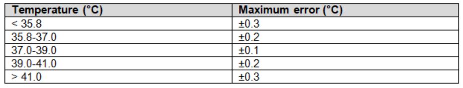
Table 1: Requirements for temperature accuracy under ASTM E1112-00(2016)
Beyond selecting an accurate temperature sensor, achieving true ±0.1°C accuracy in a clinical temperature probe or a wearable temperature patch can be challenging for the following reasons:
- Low power: At this level of accuracy, even transient power consumption on the order of microwatts (µW) can be enough to heat a sensing element outside of the ASTM E1112 required range.
- Thermal design: As a designer, even after you’ve calibrated and verified the overall accuracy of your system, it’s still possible for external environmental factors to affect the sensor or measurement, such as physical shock or a change in pressure, to cause the thermal path to be less conductive due to loss of contact with the skin, resulting in a loss of accuracy.
In this post, I’ll discuss fundamental design considerations in selecting the sensing element for wearable temperature monitoring systems, and, ultimately, monitoring temperature to accurately measure the temperature of patients.
Selecting a Sensing Element
Before you can measure anything, you need to select the correct sensing element for your temperature probe or patch. Common temperature-monitoring sensor types include thermistors or integrated circuit (IC) temperature sensors. It is imperative that the sensor you choose is reliable in the system and helps maintain a consistent accuracy of ±0.1°C for the overall system.
While thermistors provide a manageable balance of cost and power consumption, they often require calibration to achieve medical accuracy and can be prone to failure due to shifts in the resistance from shock or humidity. IC temperature sensors have only recently been able to guarantee ±0.1°C accuracy, but provide the additional benefits of factory calibration, lower power consumption and digital interfaces to simplify system integration.
Designing for Minimal Temperature Error
Regardless of your choice of sensing element, when designing a patch for this level of accuracy, remember these two key factors:
- The sensor must make suitable patient contact to assure effective thermal contact. .
- The sensor must be thermally isolated from all other heat sources.
1. Making Good Thermal Contact
When taking external measurements with temperature patches or skin probes, keep in mind the actual thermal path between the actual sensing element and the skin of the user. Figure 1 shows an example thermal path; in this example, the sensor has a very very thin small-outline no-lead (WSON) package. Such IC temperature sensors measure the temperature of the silicon die. For a package like this, it is best to place a copper fill under the thermal pad of the device on both sides of the board. Connecting these pads with vias provides the best possible path for conduction between the die and the skin. Do not use copper for making actual contact with the skin because of its tendency to corrode. Instead, use a biocompatible material coating such as gold over the pad or coat the point of contact with thermally conductive polymer, which will provide more reliable thermal conduction.
 Figure 1 Thermal stack-up example for skin temperature measurement using a WSON package
Wearable temperature-sensing patches should always be in a flex or semi-rigid printed circuit board (PCB) design. In the case of semi-rigid designs, it’s important to place the sensing element on the flex side of the PCB and minimize the thickness of the flex board as much as possible. This reduces the thermal resistance between the surface of the skin and the sensor, and a thinner board will flex more easily and make better contact.
For the temperature patch shown in Figure 2, the board thickness is approximately 6.8 mils. This patch is designed to be worn with a clear adhesive bandage over it, to keep the sensor and contact pad from lifting away from the skin and reducing the measurement accuracy. Alternatively, some newer temperature patch designs – such as this innovation – print circuit traces directly onto adhesive bandages, allowing for extremely thin form factors and excellent physical contact with the patient.
 Figure 2 Use flex PCB designs with strong adhesive coverings or backings to avoid lifting the sensor away from the skin
2. Thermal Isolation from Other Heat Sources
If you want the skin to be the true thermal source for your sensing element, then you need to remove heat from other sources. All electronic components will give off some amount of heat –and in general more power translates to more heat – so you will need to ensure that your sensor is as far away as possible from higher-power components.
Figure 3 shows a thermal capture of heat distribution through the air from a 100°C power resistor. For body temperature-monitoring systems, this type of heat generation would be impossible to compensate for, not to mention dangerous for the patient. As you build your temperature monitoring solution, it is important to consider components that are power intensive. Such components need to be placed farther away from the sensing element to have minimal to no impact on the sensor data.
 is 15.24 mm") Figure 3 Thermal capture of a board with an IC temperature sensor and power resistor; the distance (D) is 15.24 mm
Figure 3 Thermal capture of a board with an IC temperature sensor and power resistor; the distance (D) is 15.24 mmConclusion
Medical accuracy for patient temperature monitors poses some difficult thermal challenges. With the right sensor, you can overcome these difficulties with just a little understanding of how to take advantage of the placement and layout of your system.
Additional Resources
- Check out the TMP117M, TI’s ultra-high-accuracy ±0.1°C temperature sensor for medical applications.
- Jump-start your TMP117M development with the high-accuracy wireless wearable temperature sensor reference design.
- Read temperature patch design in these application notes:
- Watch the Wearable, wireless, multiparameter patient monitor for medical video about TI’s wearable temperature patch design.
- Watch the wearable patch demo video to learn how to use the TMP117 in a SimpleLink™ Bluetooth-enabled skin temperature patch.