SSZT569 december 2018 DRV8800 , DRV8801 , DRV8835 , DRV8837 , DRV8837C , DRV8848 , MSP430FR2111
Other Parts Discussed in Post: DRV8848 MSP430FR2111 DRV8800 DRV8801
In part 1 of this series, my colleague Shreenidhi Patil discussed the two most popular types of latching relays used in smart meters: a single-coil relay and a dual-coil relay. In this installment, I will explore TI’s offerings for relay-driving applications, including typical schematics and waveforms. Also, for an application-level understanding, I will discuss two use cases for operating the relays: separately with <20 V for each relay; and in parallel, with a relay operating voltage <20 V.
| Reference designs and products for e-meters | |

|
Learn more about our products and reference designs for electricity meters |
Figure 1 is an overview of TI’s available motor/relay driver offerings.
 Figure 1 TI’s Available Motor/relay
Drivers
Figure 1 TI’s Available Motor/relay
DriversTwo Relays Driven Separately Using the DRV8848 (for Single- and Dual-coil Relays)
The main difference between driving two relays separately (as opposed to driving them in parallel) is the number of full H bridges required. Driving two relays in parallel requires only one full H bridge. Driving two relays separately requires two full H bridges with individual control. Figure 2 is a simplified schematic of TI’s DRV8848 for operating dual- and single-coil relays.
 Figure 2 Simplified Schematic of the DRV8848 for Dual- and Single-coil Relays
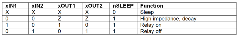
Table 1 shows the truth table for driving relays with the DRV8848 (x = A or B).
|
For a single-coil relay, the two ends of the low-voltage coil connect across AOUT1 and AOUT2, as shown in Figure 2. The 100-ms pulse on IN1 makes the corresponding AOUT1 high and the AOUT2 pin low, as shown in Figure 3. This results in a current flow through the coil, causing the relay to toggle from the off state to the on state. The 100-ms pulse on IN2 makes the corresponding AOUT2 high with AOUT1 low, causing the relay to toggle from the on state to the off state.
 Figure 3 Pulse vs. Relay Current
Waveform: Green Waveform = IN1; Yellow Waveform = Current across AOUT1 to
AOUT2
Figure 3 Pulse vs. Relay Current
Waveform: Green Waveform = IN1; Yellow Waveform = Current across AOUT1 to
AOUT2For a dual-coil relay, you need to connect the common point of the two coils to the available Vs power supply, which is used to drive the relay and the other two ends of the coil to AOUT1 and AOUT2, respectively, as shown in Figure 2. In this case, however, the sleep pin puts OUT1 and OUT2 in high Z mode. Toggling the sleep pin, along with keeping IN1 and IN2 in their respective states, will result in the relay toggling to the required state.
We tested the operation of two relays being driven separately using the DRV8848 evaluation module (EVM), while being powered from a 12-V supply. Figure 4 shows the schematic for the DRV8848 EVM. One of the relays connects between AOUT1 and AOUT2, and the second relay connects between BOUT1 and BOUT2. We used the MSP430FR2111 (controller) LaunchPad™ development kit to interface with input pins AIN1, AIN2, BIN1 and BIN2. Giving a high pulse on any of the xIN1 and xIN2 pins will cause the corresponding xOUT1 and xOUT2 pins to go high, as listed in Table 1. Set the Rsense value on AISEN and BISEN according to the current trip point value (see the DRV8848 data sheet for the proper calculation).
 Figure 4 Schematic of the DRV8848 EVM
The required waveforms are captured while alternatively toggling the relay on and off.
Figure 5 shows the output coil voltage of AOUT1/AOUT2 and the current flow through the relay coil.
; Green = AOUT1 (5 V/div); Purple = AOUT2 (5 V/div)") Figure 5 Output Voltage vs. Current through the Relay: Yellow = Current through the Relay (OUT1 to OUT2, 270-mA Peak Current for Operation); Green = AOUT1 (5 V/div); Purple = AOUT2 (5 V/div)
Figure 5 Output Voltage vs. Current through the Relay: Yellow = Current through the Relay (OUT1 to OUT2, 270-mA Peak Current for Operation); Green = AOUT1 (5 V/div); Purple = AOUT2 (5 V/div)Figure 6 shows the output coil voltage AOUT1/AOUT2, input voltage AIN1/AIN2 and the current flow through the relay coil.
; Green = AOUT1/AOUT2 (5 V/div);") Figure 6 Input Voltage, Output Voltage and Current through the Relay: Yellow = Current through the Relay (OUT1 to OUT2, 270-mA Peak Current for Operation); Green = AOUT1/AOUT2 (5 V/div);
Figure 6 Input Voltage, Output Voltage and Current through the Relay: Yellow = Current through the Relay (OUT1 to OUT2, 270-mA Peak Current for Operation); Green = AOUT1/AOUT2 (5 V/div);Purple = AIN1/AIN2 (Complementary Metal-oxide Semiconductor [CMOS] Input, 5 V/div)
Figure 7 is a photograph of the actual setup of the DRV8848 EVM with two single-coil relays.
 Figure 7 Setup Showing the DRV8848 EVM and Two Single-coil Relays
Driving Two Relays in Parallel Using the DRV8800/1 (for Single- and Dual-coil Relays)
When driving two relays in parallel, only one H bridge and a DRV8800/1 serves the application as it has one H bridge. Figure 8 shows a simplified schematic of the DRV8800/1 for operating dual- and single-coil relays.
 Figure 8 Simplified Schematic of the DRV8800/1 for Dual- and Single-coil Relays
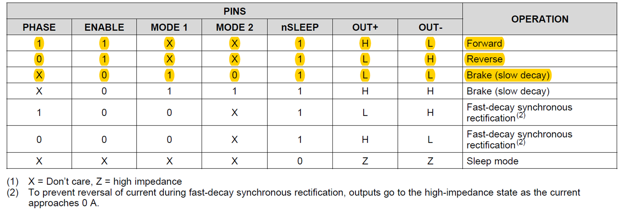
For single-coil relays, two pins – phase and enable – control the operations of the relay for the DRV8800/1. In the default or rest states, enable is kept low. As shown in Table 2, this causes OUT+ and OUT- to be low. When engaging or releasing the relay, the phase is either 1 (high) or 0 (ground), based on whether it is to be engaged or released, followed by a 100-ms pulse on the enable pin. This causes the DRV8801 to come out of the disable state and causes OUT+ and OUT- to go into the required state based on the phase pin logic, as mentioned in first two rows of Table 2.
|
For driving a two-coil relay, the connections shown in Figure 8 apply. Connect the common end of the coil to the bench power supply and the other two ends to OUT+ and OUT-. You will need to use the sleep pin and phase pin to apply the control logic from the controller and follow Table 2.
My colleague Shreenidhi and I tested the operation of two single-coil relays driven in parallel using the DRV8801 EVM; the single-coil relays have a 12-V rating. The DRV8800/1 can be used for relay coil voltage up to 38V. Figure 9 shows the schematic for the DRV8800/1 EVM.
 Figure 9 DRV8801 EVM Schematic
The relay is connected across OUT+ and OUT- and control is given via phase and enable. Phase sets the direction of toggle, whereas enable has a 100-ms pulse to operate the relay. The nSLEEP pin pulls high. Connect a sense resistor per the required current trip point (see the DRV8800/1 data sheet for more calculations regarding the actual value to connect at the sense pin). MODE1 is tied to 3.3 V and MODE2 is shorted to ground.
The MSP430FR2111 (controller) LaunchPad development kit interfaces with the phase and enable input pins of the DRV8801 EVM. Alternatively toggling the relay on and off captures the required waveforms. Figure 10 shows waveforms for the phase and enable input pins and the current flow through the relay coil.
; Purple = Phase (1 V/div); Green = Enable (2 V/div)") Figure 10 Phase, Enable and Current through Relay Waveforms: Yellow = Current through Relay Coil (100 mA/div); Purple = Phase (1 V/div); Green = Enable (2 V/div)
Figure 10 Phase, Enable and Current through Relay Waveforms: Yellow = Current through Relay Coil (100 mA/div); Purple = Phase (1 V/div); Green = Enable (2 V/div)Figure 11 shows waveforms for the output pins of the DRV8801’s OUT+ and OUT- and current through the relay coil.
; Purple = OUT+ (5 V/div); Green = OUT- (5 V/div)") Figure 11 OUT+ and OUT- and Current through Relay Waveforms: Yellow = Current through Relay (100 mA/div); Purple = OUT+ (5 V/div); Green = OUT- (5 V/div)
Figure 11 OUT+ and OUT- and Current through Relay Waveforms: Yellow = Current through Relay (100 mA/div); Purple = OUT+ (5 V/div); Green = OUT- (5 V/div)Figure 12 is a photograph of the actual setup of the DRV8801 EVM with two single-coil relays.
 Figure 12 Setup Showing the DRV8801 EVM and Two Single-coil Relays
The two most popular types of latching relays used in smart meters are the single-coil relay and the dual-coil relay, and TI offers a wide range of motor/relay driver ICs for operating both single- and dual-coil, including the DRV8848 and DRV8800/1.
Additional Resources
- Download the DRV8800 data sheet.
- Read these application reports: