SSZT571 december 2018 TPS92692-Q1
This is the second installment in a two-part series on designing bright daytime running lights (DRLs) without the need for two LED drivers, a method provided in the Automotive Daytime Running Light Dual String LED Driver Reference Design with Current Balancing.
In the first installment of this series, “Designing daytime running lights, part 1: adding one-fail-all-fail LED fault detection,” I outlined two ways to achieve the desired brightness in LED headlights, provided an overview of the reference design and explained how to detect a fault.
Once a fault is detected, the reference design needs a way to identify when VDrain is greater or lesser than the voltage, given by Equation 1:
VDrain=IMirror*(MOSFET rdson+R0)= Vf+IMIRROR*R0 (1)
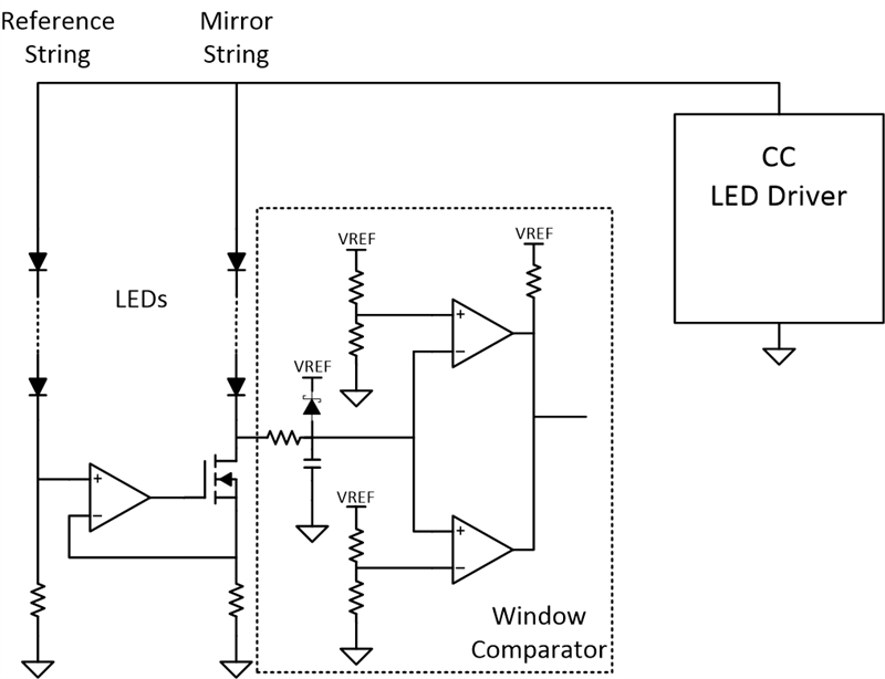
You can accomplish this by implementing a window comparator circuit made up of open-drain or open-collector comparators, as shown in Figure 1.
 Figure 1 Window Comparator
The resistor dividers on the reference inputs of the top and bottom comparators set the upper and lower limits of the “window,” respectively. When VDrain is between these upper and lower limits, the output of the window comparator is high (VREF). When outside of the limits of the window voltage, the output pulls low to ground. In the reference design, the upper and lower thresholds of the window are ~110% and ~90% of the voltage given by Equation 1, respectively.
The window comparator can detect all of the LED faults mentioned in the first part of this series. However, in the case of an open circuit in the reference string fault, oscillations of VDrain will cause the window comparator to trip repeatedly. Because of this reason, you must latch the window comparator output to ensure that its output remains low the first time VDrain is outside of the window voltage thresholds.
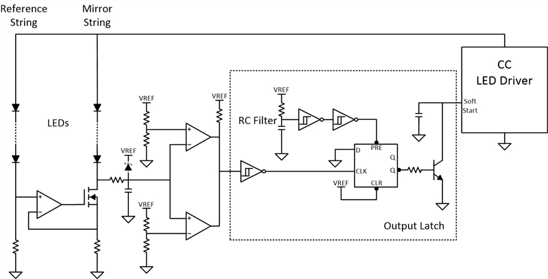
In DRL modules that use microcontrollers, you can use software in the microcontrollers to latch the fault. In DRL modules without microcontrollers, you can use the circuit shown in Figure 2 to latch the window comparator output and disable the LED driver when a fault occurs. The latch circuit in Figure 2 uses a Schmitt trigger and a D flip-flop.
 Figure 2 Output Latch
When a fault occurs, the output of the window comparator will transition from high to low. The D flip-flop transfers data from its input D to its outputs Q and at each rising edge of its CLK input. For this reason, an inverting Schmitt trigger is used to translate a falling edge at the output of the window comparator into the the rising edge required by the D flip-flop.
The design uses a D flip-flop with preset and clear pins that enable confirmation of the initial device conditions at startup. The truth table shown in Figure 3 shows that when is low and is high, Q and are high and low, respectively. With low, the N-channel P-channel N-channel (NPN) transistor connected to the soft-start pin on the LED driver does not conduct, thus allowing the LED driver to operate as intended at startup.
 Figure 3 D Flip-flop with Preset and
Clear
Figure 3 D Flip-flop with Preset and
ClearThe resistor-capacitor filter and two series-inverting Schmitt triggers cause the pin to be low at startup. After VCC charges the capacitor to the threshold of the first inverting Schmitt trigger, will transition high and the device will operate as expected.
With low at startup and D tied directly to ground, if a fault occurs you will see a rising edge at the CLK input and will transition from low to high. This causes the NPN transistor to conduct and pull the soft-start pin on the LED driver to ground. As shown in the TPS92692-Q1 data sheet, if the soft-start pin pulls to ground, the driver will stop switching and stop the LED current flow.
Lab Results
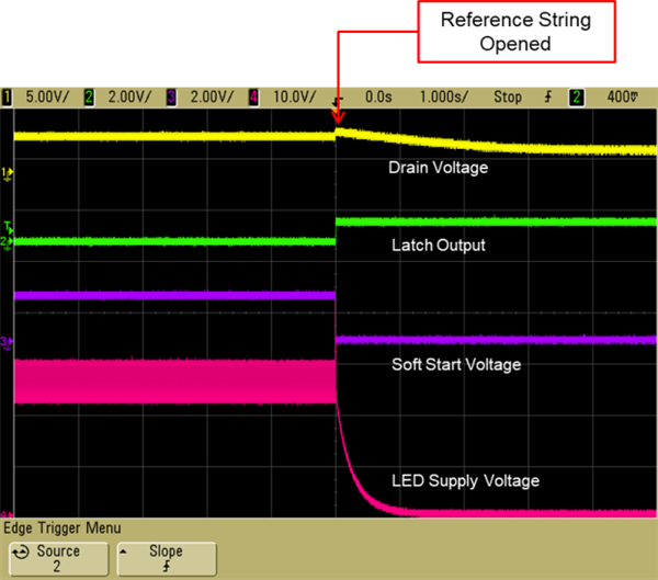
I tested this in the lab with hardware from the reference design. Figure 4 shows the result of an open circuit in the reference string.
 Figure 4 An Open Circuit in the
Reference String
Figure 4 An Open Circuit in the
Reference StringYou can see a spike in the drain voltage when the reference string opens. This causes the output of the latch to transition high, which in turn pulls the soft-start pin on the LED driver to ground and shuts off current flow to the LEDs. There are no oscillations at the drain because the LED driver shuts off immediately.
Conclusion
LEDs are an energy efficient choice for daytime running lights, and with the reference design for parallel strings, you can achieve optimal brightness without the need of a second LED driver.
Additional Resources
- Review the Window Comparator Reference Design.
- Read the white paper, “Evolution vs. revolution: the building blocks of automotive body electronics.”