SSZT587 november   2018 LM73605


  1.   1
  2.   2
    1.     3
    2.     Example
    3.     Step 1: Use the Design Calculator to Determine Resistor Values
    4.     Step 2: Simulate the Values Using TINA-TI Software
    5.     Step 3: Validate on an EVM
    6.     Conclusion

Reed Kacz

Is enable hysteresis not included in the DC/DC converter you are designing with? Or is the built-in enable hysteresis too small?

Modern DC/DC converters use an enable pin to control the design conditions at which the power supply turns on and off. It is possible, however, to add an adjustable hysteresis to your DC/DC converter’s enable signal. You can replicate this technique using Excel spreadsheet calculations, Texas Instruments (TI) TINA-TI™ software simulations and evaluation module (EVM) testing.

It is standard electrical engineering practice to add a hysteresis resistor around a comparator (adding feedback). You can apply this same idea to a DC/DC converter by adding a resistor connecting the enable signal to the output voltage. By adding the output voltage to the enable signal, the enable signal will be pulled even higher once the converter produces an output. Figure 1 shows a simplified schematic.

GUID-000F32DF-7F30-47A8-A73E-7D745B756556-low.png Figure 1 Simplified DC/DC Converter Schematic

You can use Equations 1 through 4 to calculate the correct resistor values based on the design parameters:

GUID-21FCBA66-F0B6-4496-94D1-83B92EF081E9-low.png

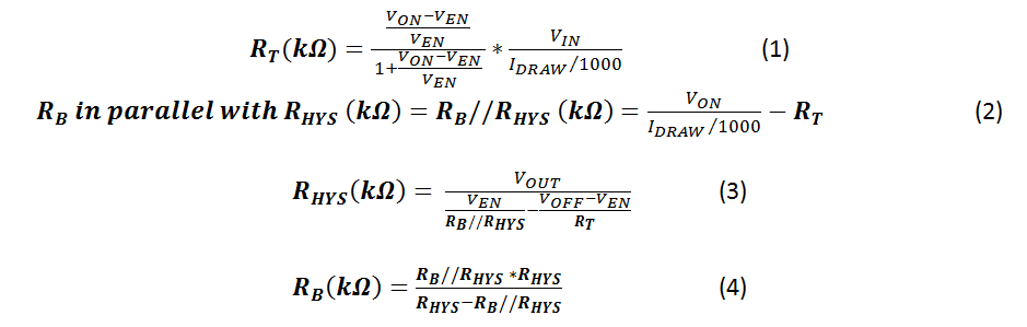
where RT is the top feedback resistor in the enable resistor network, RB is the bottom feedback resistor in the enable resistor network, VON is the desired input voltage for turnon, VOFF is the desired input voltage for turnoff, RHYS is the hysteresis resistor, IDRAW is the current drawn by the enable resistor network and VEN is the enable threshold voltage (a data-sheet specification).

Example

In this example, the converter will be enabled once the input voltage reaches 10V. Once on, the input voltage will decrease down to 7.5V before the converter becomes disabled. This means designing a system hysteresis of 2.5V into the enable signal. The specific design parameters are:

  • VIN typical = 12V.
  • VON = 10V.
  • VOFF = 7.5V.
  • VOUT = 5V.
  • VEN = 1.2V (no internal hysteresis).

Now let’s look at the calculations, simulations and test data for this additional hysteresis.

Step 1: Use the Design Calculator to Determine Resistor Values

The Excel design calculator can calculate the resistor values corresponding to your desired design parameters. In the yellow boxes (Table 1), enter the preferred turnon voltage, the amount of added hysteresis, the VEN threshold, the total desired current draw and the output voltage. Use the enable resistor network current draw entry to select how much current you will budget for the enable network. By selecting a smaller value, the resistor magnitudes will increase. Enter this value in microamperes.

Table 1 Example Using Excel Design Calculator

GUID-17CE72C5-CB1F-4BBC-B3EB-31A6BB45A7BA-low.png

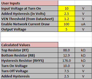
The Excel calculator quickly recommends the appropriate component values for the desired VON and VOFF. Table 1 also shows the calculated RT, RB and RHYS values to meet the input criteria.

Step 2: Simulate the Values Using TINA-TI Software

You can use a TINA-TI simulation in order to simulate turnon and turnoff performance with the calculated resistor values. Adjust RT, RB, RHYS, VEN and VOUT amplitude to match your design calculations. Figure 2 shows the TINA-TI Simulation schematic that can be adjusted to test out different values.

GUID-9D660874-56AE-4BA7-94E0-46F59D1DDE8F-low.png Figure 2 TINA-TI Simulation Schematic

Click Analysis and then Transient Analysis to run the simulation. Running from 750ms to 1.75s will show a full turnon, turnoff cycle. Figure 3 shows the simulation results.

GUID-7A0D6357-AE44-44F5-B8FA-25FBF1BD47D2-low.png Figure 3 TINA-TI Simulation Transient Results

Step 3: Validate on an EVM

Wiring in the hysteresis resistor to a TI EVM will allow you to test in the lab. For this example, I used the TI LM73605 EVM with a small resistive load and a signal generator to provide the input ramp waveform. Figure 4 demonstrates the physical implementation of the hysteresis example with results measured on an oscilloscope.

GUID-7626DC6A-5ACF-4166-B19A-242E1C6D441B-low.png Figure 4 EVM Testing Results

Conclusion

The Excel calculator allows for quick design of a hysteresis network. The simulation files prove the mathematical validity, showing the same turnon and turnoff threshold as the calculator. Finally, testing in the lab proves that at the applications level, the turnon and turnoff thresholds are very close to the ideal, corresponding to the calculator. The Excel calculator, simulation tools and EVM testing provide a quick and accurate method to add hysteresis to your DC/DC converter.

For your next DC/DC power design, download the enable hysteresis Excel calculator and enable hysteresis TINA-TI simulation to help fast-track your added power-stage hysteresis.