SSZT597 october 2018 THS3491
With technology emerging on a daily basis, there’s an ever-growing demand to generate faster high-voltage signals, and the requirement is often driven by the end equipment. These end equipments can be anything from increasing the speed of an arbitrary waveform generator (AWG) and high-voltage clock generators to driving the input of power field-effect transistors or semiconductor test equipment.
The increased speed requirements from high voltage and current put immense pressure on the last-stage output driver amplifier to not distort the high-frequency sinusoidal signal while still being within the thermal limits of operation. High-voltage, high-frequency signal generation becomes even more challenging for an output amplifier when a low-resistive or high-capacitive load drive is involved; the amplifier can become limited in its maximum linear output current drive when you need a high voltage swing at a high frequency. Slew-rate limitations cause an increasingly distorted output signal, and the amplifier cannot source or sink the required output current at high frequencies.
In this post, I’ll focus on improving the distortion performance of a high-voltage, high-frequency sinusoidal signal while driving a low-resistive or high-capacitive load.
To understand the slew-rate limitation, I slightly modified the slew-rate equation for large-signal bandwidth in terms of peak output current (IP), as shown in Figure 1:
 Figure 1 Equation 1
where f3dB is the -3-dB bandwidth of the amplifier for a given peak output voltage (VP) and RLOAD is the total resistive load at the amplifier’s output.
To maintain a constant slew rate, IP should increase for a given VP with RLOAD. Depending on RLOAD, this linear output current requirement could be quite significant, which automatically places severe constraints on the amplifier’s output current drive capability while limiting high-frequency operation. For capacitive loads, the effect of reduced linear output current is even more pronounced because of reducing impedance with increased frequency.
An effective way to counter this output current drive limitation is to use load sharing to boost the drive. The concept of load sharing is to have multiple parallel amplifiers drive a shared output load, where each amplifier is driven by the same input source (VIN), as shown in Figure 2. Driving a shared output load with multiple parallel amplifiers effectively reduces the output current requirement of each amplifier by 1/N, where N is the number of parallel amplifiers. Each parallel amplifier’s output is at the same voltage because they are driven from the same VIN.
 Figure 2 N Parallel THS3491 Amplifiers
in a Load-sharing Configuration
Figure 2 N Parallel THS3491 Amplifiers
in a Load-sharing ConfigurationAssuming that the feedback (RF), gain (RG) and output series resistor (RS1) are perfectly matched, Figure 3 gives the input-to-output transfer function at the individual amplifier’s output VO(i):
 Figure 3 Equation 2
where i = 1 to N amplifiers in a load-sharing configuration.
Figure 4 expresses the input-to-output transfer function at VOUT of the resistive load (RL1):
 Figure 4 Equation 3
where which is the combined output load of N amplifiers in a load-sharing configuration.
Figure 5 calculates the individual amplifier output current drive for N amplifiers in a load-sharing configuration:
 Figure 5 Equation 4
Let’s take an example of a single THS3491 amplifier driving an RLOAD of 20 Ω at 20 VPP. The required output current drive in this scenario is ±500 mA. Operating from ±7 V to ±15 V, the THS3491 offers 900-MHz bandwidth while achieving a 20-VPP output voltage swing at 100 MHz and driving an RLOAD of 100 Ω. Even though the THS3491 can support a peak output current of ±500 mA, its output can look distorted (or triangular) on a scope because slew-rate limitations prevent the ability to source/sink the required output current at high frequencies. (This reduction in output current across frequency is true for any high-output-current operational amplifier [op amp].) Using two THS3491 amplifiers in a load-sharing configuration splits the output current drive equally between the two amplifiers at ±250 mA, resulting in a less distorted output waveform across frequency.
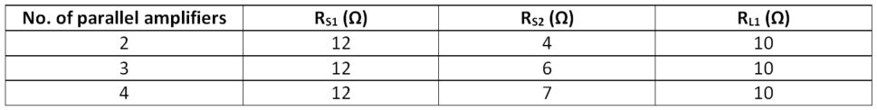
Figure 6 and Figure 7 show second (HD2) and third harmonic (HD3) measurements, respectively, comparing two, three and four THS3491 parallel amplifiers while driving 20 VPP with an RLOAD of 20 Ω. Table 1 lists the respective series and shunt resistor values used to create an RLOAD of 20 Ω. As you can see from the distortion plots, there is clearly an advantage of improved distortion performance in the load-sharing configuration. The harmonic distortion degrades beyond -30 dBc at 60 MHz with two parallel amplifiers. However, with three or four parallel amplifiers, the output current drive strength extends well beyond 100 MHz for the same 20-VPP output swing.
 Figure 6 HD2 vs. Frequency for Parallel
THS3491 Amplifiers; Test Conditions: vO = 20 VPP,
RLOAD = 20 Ω
Figure 6 HD2 vs. Frequency for Parallel
THS3491 Amplifiers; Test Conditions: vO = 20 VPP,
RLOAD = 20 Ω Figure 7 HD3 vs. Frequency for Parallel
THS3491 Amplifiers; Test Conditions: vO = 20 VPP,
RLOAD = 20 Ω
Figure 7 HD3 vs. Frequency for Parallel
THS3491 Amplifiers; Test Conditions: vO = 20 VPP,
RLOAD = 20 Ω
|
You can deduce two things from this load-sharing approach:
- Each additional amplifier now has to output less current for the same output voltage swing, extending the frequency of operation beyond the f3dB point.
- An increase in the number of parallel amplifiers enables the circuit to drive a heavier output load for the same output swing and operating frequency. This is because of the increased output current boost offered by parallel amplifiers.
One thing to note is that the use of load-sharing configuration has the disadvantage of reduced stability because of the increased capacitive load caused by long input and output printed circuit board (PCB) signals. Output push/pull current mismatching with increased system power dissipation is another byproduct of this approach. All of these factors will eventually determine the maximum number of parallel amplifiers that you can add.
Additional Resources
- Download the THS3491 data sheet.
- Learn more about load sharing with the Reference Design for Implementation of the Load Sharing Concept for Large-Signal Applications.
- Search TI high-speed op amps and find technical resources.