SSZT601 october 2018 LMR14030-Q1
Designers often use several DC/DC buck converters in automotive systems to support the multiple power rails. There are several considerations when selecting these types of buck converters, however. For example, you need to select high-switching-frequency DC/DC converters (operating above 2MHz) for automotive infotainment/head units to avoid interference with the radio AM band, and you also need to reduce solution size by selecting relatively smaller inductors. In addition, high-switching-frequency DC/DC buck converters can also help reduce the input current ripple to optimize the size of input electromagnetic interference (EMI) filters.
However, compliance with required EMI standards is critically important for major automotive original design manufacturers (ODMs) who are trying to build the newest systems for cars. The requirements are very stringent, and manufacturers must comply with standards like Comité International Spécial des Perturbations Radioélectriques (CISPR) 25. In many cases, if the manufacturer doesn’t meet the standard, automakers cannot accept the design.
Thus, choosing a layout for a DC/DC buck converter is key. Optimizing the power loop through which high current flows through is very critical to achieve good EMI performance.
Taking the LMR14030-Q1 DC/DC buck converter as an example, Figure 1 and Figure 2 show two different printed circuit board (PCB) layouts for a dual-channel buck converter. The red line shows how the power loop flows in layout. The flow direction of the power loop in Figure 1 is a U type and in Figure 2 is an I type. These two kinds of layouts are the most common in automotive and industrial application systems. So which one is better?
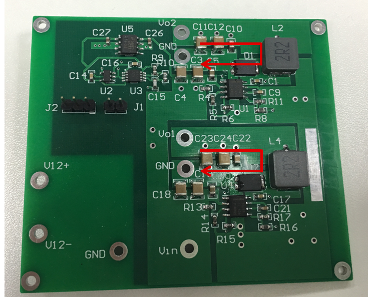 Figure 1 A U-type Layout
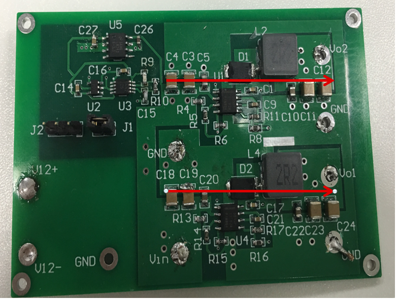 Figure 2 An I-type Layout
Conducted EMI is sub-divided into differential-mode and common-mode categories as the two modes are similarly measured but controlled through different methods. Differential-mode noise is derived from the rate of current change (di/dt), while common-mode noise is generated from the rate of voltage change (dv/dt). The critical point for EMI performance is how to make the parasitic inductance as small as possible.
Figure 3 is an equivalent circuit for a buck regulator. Most designers know how to make Lp1, Lp3, Lp4 and Lp5 as small as possible but ignore Lp2 and Lp6. A U-type layout has a smaller parasitic inductance on Lp2 and Lp6 compared to an I-type layout. In a U-type layout, when the high-side metal-oxide semiconductor field-effect transistor (MOSFET) turns on, a shorter power loop will contribute to better EMI performance.
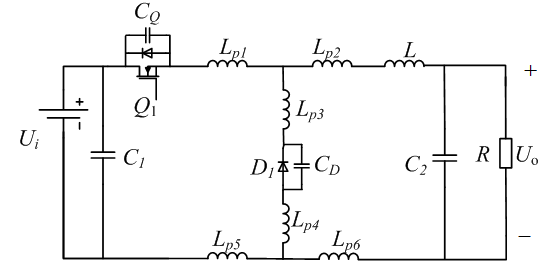 Figure 3 Buck Regulator Equivalent
Circuit
Figure 3 Buck Regulator Equivalent
CircuitIn order to verify what the best layout is, measuring the EMI data is essential. Figure 4 and Figure 5 compare the conducted EMI. As you can see, the EMI performance for the U-type layout is better than the EMI performance for the I-type layout, especially at high frequencies.
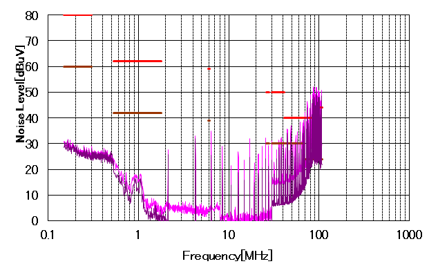 Figure 4 U-type EMI Performance in
Phase-shift Mode
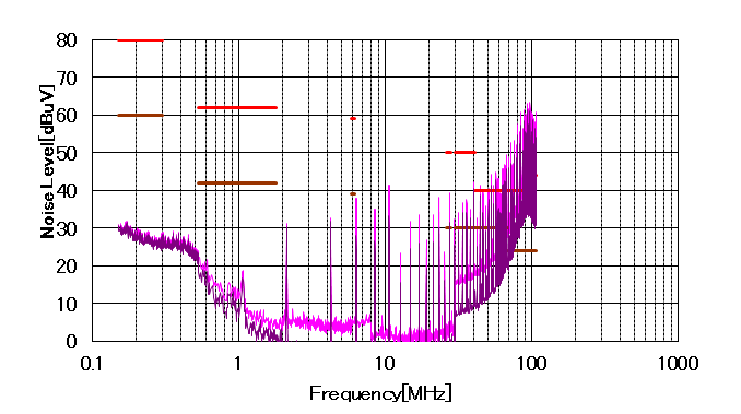 Figure 5 I-type EMI Performance in
Phase-shift Mode
Figure 5 I-type EMI Performance in
Phase-shift ModeAdding a filter is an effective way to improve EMI performance. Figure 6 shows a simplified EMI filter, which includes a common-mode (CM) filter and a differential mode (DM) filter. Generally, the DM filters noise less than 30MHz and the CM filters noise from 30MHz to 100MHz. Both filters have an effect on the entire frequency band where EMI needs limiting. Figure 7 and Figure 8 compare the conducted EMI with both a common-mode filter and a differential-mode filter. The U-type layout can pass CISPR 25 Class 3 standards, but the I-type layout cannot.
 Figure 6 A Simplified EMI
Filter
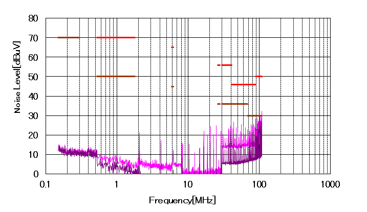 Figure 7 U-type EMI Performance Using a
DM and CM Filter
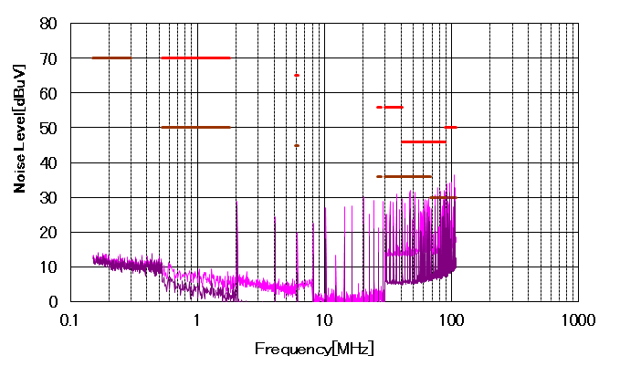 Figure 8 I-type EMI Performance Using a
DM and CM Filter
Figure 8 I-type EMI Performance Using a
DM and CM FilterAs you can see, a U-type layout achieves better EMI performance than an I-type layout. See the application note “How SYNC Logic Affects EMI Performance for Dual-Channel Buck Converters” for more information.