SSZT617 october 2018 TPS65987D
As USB Type-C™ and USB Power Delivery (PD) gain momentum across a broad set of products, more and more engineers are rolling up their sleeves and making plans to add USB Type-C to their newest designs. It can be a bit overwhelming to start a new design with a fairly new technology.
USB Type-C combines power, video and data on a single connector. Researching components and specifications of each new feature requires a great deal of time and skill. So I want to spend some time looking at a very complex use case and showcase how to build the solution with “no assembly required.”
First of all, what do I mean by no assembly required? It’s just a play on words to highlight the typical challenge associated with adding power, video and data to a single port. Assembly language is a tedious, time-consuming endeavor, and most non-TI solutions require a process that’s just as cumbersome. Engineers must write software or firmware to control the various aspects required to bring these three technologies together, and it really can get quite complex. After a detecting a USB Type-C cable, you’ll need to enable the appropriate power supply with the correct voltage; query the cable to identify its capabilities; determine the capabilities of the device on the far end; and configure both the external multiplexer and the DC/DC converter.
Easy, right?
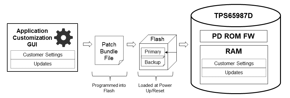
Well, it can be. TI does not expect you to learn how to program the TPS65987D, for example, or read mountains of USB specifications. The TPS65987D is a configurable device. Pre-programmed, Underwriters Laboratories (UL)/International Electrotechnical Commission (IEC)-certified and USB Implementers Forum-compliant, the TPS65987D requires only a few mouse clicks to select the desired power, video and data profiles. At boot, the configuration file is loaded via flash or an external processor, transforming the device into a full-featured, tailored solution.
 Figure 1 TI Configuration Model
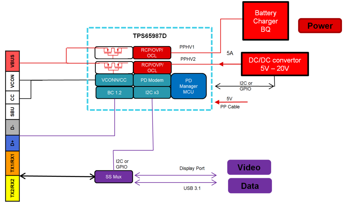
Figure 2 is a block diagram of a solution using TI’s TPS65987D. It integrates the power paths for both source and sink operation. The onboard firmware and analog circuits monitor and direct the proper operation of the power path. Simple inputs from a graphical user interface (GUI) allow you to select the voltage and current levels available and then tie in the associated general-purpose input/output (GPIO) or I2C writes needed to control external devices. See? No assembly required.
A simple-to-use GUI also facilitates USB Type-C and USB PD negotiation. Just select the USB Type-C and USB PD capabilities required and the values will be stored for uploading during device boot. Again, no assembly required.
Negotiating the USB specification and DisplayPort™ version also takes just a couple of mouse clicks to configure. Complex pin multiplexing schemes and critical timing parameters are already implemented and sent via GPIO or I2C to an external multiplexer.
 Figure 2 Typical Notebook
Implementation
Figure 2 Typical Notebook
ImplementationImplementing complex USB Type-C and USB PD solutions does not need to be difficult. TI has a variety of compliant solutions with easy-to-use configuration options. Take a look at the TPS65987 evaluation module and its user’s guide to get started today.