SSZT742 april 2018 LMR14050 , LMR14050-Q1 , TPS65263 , TPS65263-Q1
Electromagnetic interference (EMI) is a troublesome issue in certain designs, especially in automotive systems, like infotainment, body electronics, ADAS and so on. When designing the schematic and drawing the layout, designers usually minimize noise at the source by reducing the high di/dt loop area and slowing down the switching slew rate.
However, sometimes no matter how carefully they design the layout and schematic, they are still unable to reduce the conducted EMI to required levels. The noise depends not only on the circuit parasitic but is also related to the current level. In addition, the action of switch turn-on and turn-off creates discontinuous current. Discontinuous current causes voltage ripple on the input capacitor, which increases EMI.
So it’s a good idea to consider other ways to improve conducted EMI performance – adding an input filter to smooth the voltage perturbations or adding a shield to block the noise.
Figure 1 shows a simplified EMI filter, which includes a common-mode (CM) filter and a differential mode (DM) filter. Generally, the DM filter filters noise less than 30MHz and the CM filter filters noise from 30MHz to 100MHz. Both filters have an effect on the entire frequency band where EMI needs limiting.
 Figure 1 A Simplified EMI
Filter
Figure 1 A Simplified EMI
FilterFor example, Figure 2 shows the positive and negative noise from the input wire without any filter in the infotainment system, as well as both the peak and average noise. The system tested uses TI’s SIMPLE SWITCHER® LMR14050-Q1 single channel buck converter to generate 5V at 5A and the TPS65263-Q1 triple channel buck converter to generate 1.5V at 3A, 3.3V at 2A and 1.8V at 2A. The switching frequency is 2.2MHz. The conducted EMI standard in the figure is Comité International Spécial des Perturbations Radioélectriques (CISPR) 25 Class 5.
 Figure 2 Noise without Any Filter
against the CISPR 25 Class 5 Standard
Figure 2 Noise without Any Filter
against the CISPR 25 Class 5 StandardFigure 3 shows the EMI result with a DM filter. The DM noise is attenuated nearly 35dBμV/m by the filter in the middle frequency band (2MHz to 30MHz). The high-frequency noise (30MHz to 100MHz) is also reduced, but still exceeds the limit level. That is because a DM filter does not effectively filter CM noise.
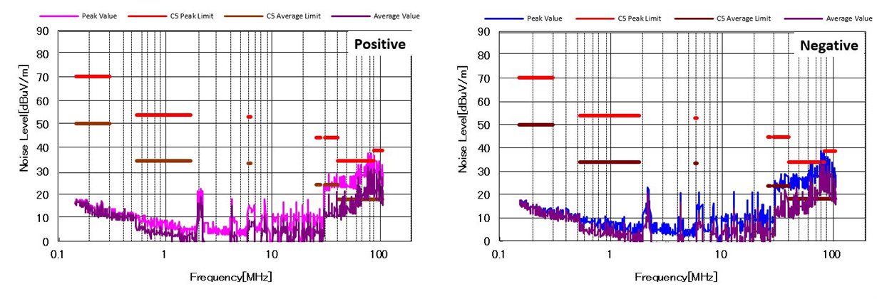 Figure 3 Noise with a DM Filter against
the CISPR 25 Class 5 Standard
Figure 3 Noise with a DM Filter against
the CISPR 25 Class 5 StandardFigure 4 shows the noise with a DM and CM filter. Compared to Figure 3, the CM filter decreases CM noise by nearly 20dBμV/m. The EMI performance passes CISPR 25 Class 5.
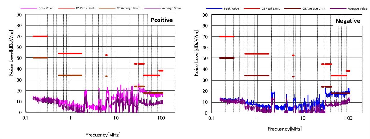 Figure 4 Noise with a DM and CM Filter
against the CISPR 25 Class 5 Standard
Figure 4 Noise with a DM and CM Filter
against the CISPR 25 Class 5 StandardFigure 5 also shows the noise with a DM and CM filter (the same filter with Figure 4), but with a different layout. Compared to Figure 4, the noise in the whole frequency band increases approximately 10dBμV/m. Even worse, the high-frequency noise exceeds the standard limit.
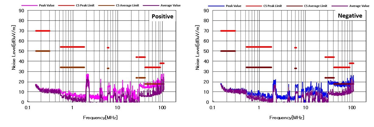 Figure 5 Noise with a DM and CM Filter
against the CISPR 25 Class 5 Standard
Figure 5 Noise with a DM and CM Filter
against the CISPR 25 Class 5 StandardFigure 6 shows the difference in the layout that caused the different results between Figure 4 and Figure 5. In Figure 5’s layout, shown on the right side of Figure 6, the large overlying copper (GND) and VIN trace form some parasitic capacitors. These parasitic capacitors provide a low impendence path for the high-frequency signal to bypass the filter. So in order to maximize the effectiveness of the filter, you must remove the overlying copper around the filter in every layer, like the layout shown on the left side of Figure 6.
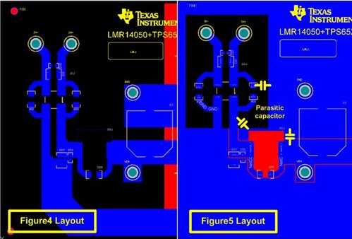 Figure 6 Different Filter
Layouts
Figure 6 Different Filter
LayoutsAnother effective way to optimize EMI performance is to add a shield. A metal shield connected to GND can block the radiated noise. Figure 7 shows the board with the suggested placement of the shield. The shield covers all components except the filters.
Figure 8 shows the EMI result with all of the filters and the shield. In Figure 8, the shield almost eliminates noise in the whole band, so the EMI performance is excellent. The shield reduces radiated noise coupling with the long input wire, which acts as an antenna. In this design, the middle-frequency noise typically couples in this way.
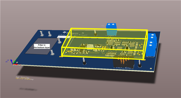 Figure 7 Board with a
Shield
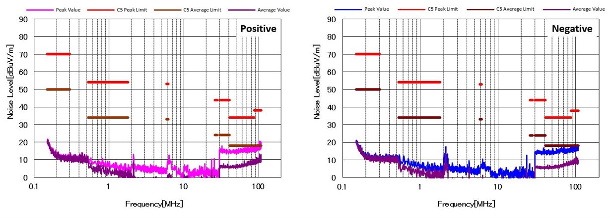 Figure 8 Noise with All Filters and
a Shield against the CISPR 25 Class 5 Standard
Figure 8 Noise with All Filters and
a Shield against the CISPR 25 Class 5 StandardFigure 9 also shows the noise with all filters and a modified shield. In Figure 9, the shield is a metal box enclosing the whole board; only the input wires are outside. With this shield, some radiated noise can bypass the EMI filter and couple to the power wires in the PCB, which results in worse EMI performance than the shield in Figure 8. Interestingly, the EMI result in the high-frequency band is almost the same as in Figure 4, 8 and 9 (they are all the same layout). That is because radiated noise is almost nonexistent in the high-frequency band for this design.
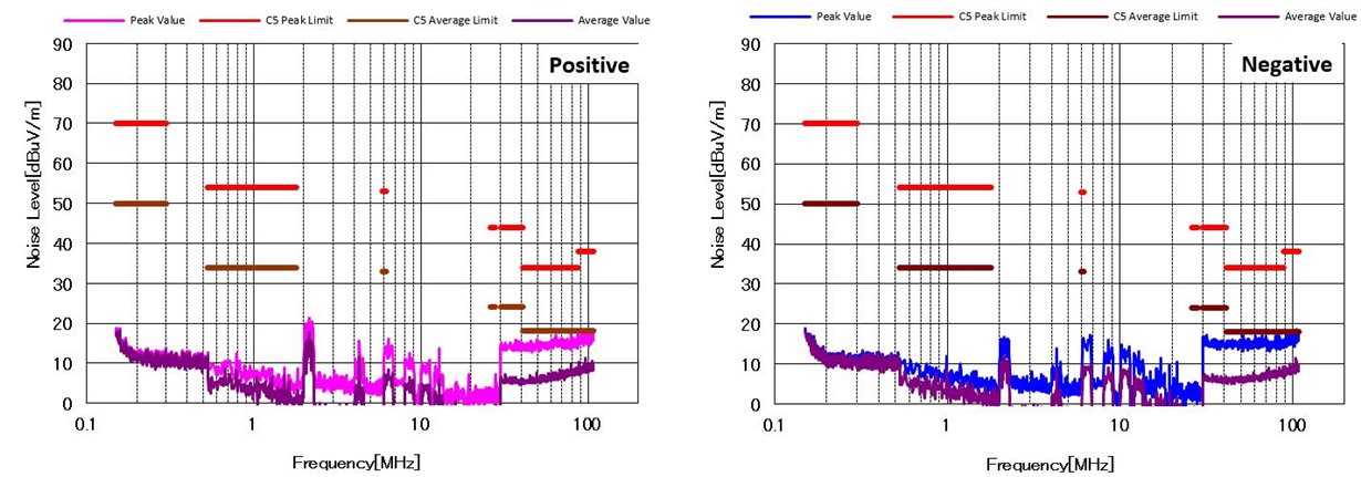 Figure 9 Noise with All Filters and a
Shield against the CISPR 25 Class 5 Standard
Figure 9 Noise with All Filters and a
Shield against the CISPR 25 Class 5 StandardIn general, adding an EMI filter and shield are both effective ways to improve EMI performance in automotive systems. At the same time, be careful with the layout of the filter and the position of the shield. Read the application note, “Low Conducted EMI Power Solution for Automotive Digital Cockpit with LMR14050 and TPS65263” for more information.